6 Connection
−
32
−
Note
•
When using the TIM output, stop the motor’s output shaft at an integer
multiple of 7.2°.
•
When switching the step angle, do this with the motor stopped and the
TIM output ON.
•
When the power is turned ON, the excitation sequence is reset to STEP
0 and the timing signal is output.
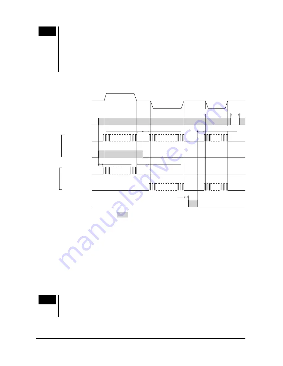
6.4 Timing chart
5 s or more
∗
3
∗
4
ON
OFF
ON
OFF
ON
OFF
ON
OFF
ON
OFF
ON
OFF
CW input
DIR input
CCW input
PLS input
AWO input
Motor operation
Power source input
100 µs or more
0.5 s or more
300 µs or more
100 µs or more
∗
2
2-pulse input mode
1-pulse input mode
∗
5
100 µs or more
∗
1
∗
1
∗
1
CW
CCW
The section indicates that the photocoupler diode is emitting light.
∗1
“100 µs or more” indicated in connection with the direction-signal select time (1-pulse
input mode) or CW/CCW pulse select time (2-pulse input mode) indicates a circuit
response time. Set it to the time required for the motor to respond to the applicable pulse
input.
∗2
The specific duration varies depending on the load inertial moment, load torque,
self-starting frequency, etc.
∗3
Do not input pulse signals immediately after switching the AWO input to OFF, given that it
will affect the motor’s starting characteristics.
∗4
After turning off the power supply, wait at least 5 seconds before turning the power supply
back on.
∗5
The
CSD2140T
,
CSD2145T
supports a 1-pulse input mode only.
Note
The
CSD2109-T
,
CSD2112-T
, and
CSD2120-T
respond up to 10 kHz with
a pulse duty of 50%. When using it at higher speeds, narrow the pulse
width (shorten the photocoupler’s ON time).


