background image

14

12.07/WE

ORGAPACK OR-P 400 HD

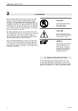
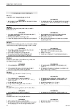
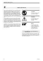
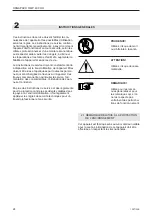
CAUTION!

Used where there is dan-

ger to life and health.

WARNING!

Used for danger which 

can cause material  


damage.

NOTE!

Used for general infor-

mation and information    

which if not followed can 

cause faults in the  


operating sequence.


GENERAL INFORMATION

These operating instructions are intended to simplify 

familiarisation with the strapping tool and the pos-

sibilities of application for the intended purpose. The 

operating instructions contain important information 

concerning the safe, proper and ef

fi

 cient use of the 

strapping tool. Observation of the information will help 

to avoid danger, reduce repairs and stoppages and 

increase the reliability and service life of the strapping 

tool.

The operating instructions must always be available 

at the place of operation of the strapping tool. They 

must be read and observed by all persons concerned 

with work on the strapping tool. This work speci

fi

 cally 

includes operation, re

fi

 lling of operating material, fault 

elimination and maintenance.

In addition to the operating instructions and the regu-

lations for accident prevention effective in the country 

of use and place of application, the recognised tech-

nical regulations for safety and proper working must 

also be observed.

      2.1 INFORMATION ON ENVIRONMENTAL           


PROTECTION

This tool is manufactured without any physical or che-

mical substances which could be dangerous to health. 

For disposal of all the parts, the governmental instruc-

tions must be observed.

Summary of Contents for OR-P 400 HD

Page 1: ...Nr From serie no A partir du no de s rie Vor dem Gebrauch des Ger tes die Betriebs anleitung aufmerksam lesen Before using the tool read the operating instructions carefully Avant l utilisation de l a...

Page 2: ...ten sowie der Richtlinie des Rates vom 22 Juni 1998 98 37 EG Maschinen Richtlinie bereinstimmt Ber cksichtigte Normen EN ISO 12100 1 EN ISO 12100 2 EN 349 EN 983 EN 1050 prEN 792 2 CH 8953 Dietikon Au...

Page 3: ...bis 1 0 mm Seite 1 Technische Daten 3 2 Allgemeines 4 2 1 Hinweis zum Umweltschutz 4 3 Sicherheitsvorschriften 5 4 Beschreibung 6 4 1 Aufbau 6 4 2 Funktionsprinzip 6 5 Inbetriebnahme 7 5 1 Druckluftau...

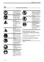
Page 4: ...paraturen und Ausfallzei ten vermindern sowie die Zuverl ssigkeit und Lebens dauer des Ger tes zu erh hen Die Betriebsanleitung muss am Einsatzort des Ger tes verf gbar sein Sie ist von allen Personen...

Page 5: ...en verwendet werden die den Sicher heitsvorschriften entspre chen Bestimmungsgem sse Verwendung Dieses pneumatische Handger t ist zum Umreifen von flachen Packst cken Spanplatten Blechpakete usw besti...

Page 6: ...etriebegeh use 8 Schweissmotor 9 Spannmotor 10 Handgriff 11 Blaue Taste Schweissen 12 Gr ne Taste Spannen 13 Roter Hebel Bandspannung l sen Fig 2 1 2 3 4 4 2 FUNKTIONSPRINZIP Festklemmen des Bandes du...

Page 7: ...tigt stets eine ausreichende Schmierung Stellen Sie den ler richtig ein und f llen Sie ihn regelm ssig auf Ohne ausreichende Schmierung bringt das Ger t niedrige oder unregel m ssige Spannung und l ss...

Page 8: ...ie ben Der Bandanfang ragt vorne ca 5 cm aus dem Ger t heraus Darauf achten dass die B nder genau bereinander liegen Spannmotor absenken Die B nder sind nun festgeklemmt und im Ger t gef hrt Spannen M...

Page 9: ...m Schmutzanfall empfielt es sich das Ger t regelm ssig t glich zu reinigen Besonders sollten das Spannrad und die Zahnplatte auf Besch digung kontrolliert und sauber gehalten werden Dies geschieht am...

Page 10: ...urch dosiertes Drehen 1 8 1 4 der Schraube im Uhrzeigersinn wird die Schweisszeit l nger im Gegenuhrzeigersinn k rzer Schweisszeit gem ss Kapitel 6 2 Abbildung 10 2 einstellen Abdeckkappe wieder aufse...

Page 11: ...ft Schutzbrille tragen Das Spannrad kann auch mit der beigelegten Spezialb rste gereinigt werden 7 5 NDERUNG DER BANDBREITE Das Ger t kann mit verschiedenen Band breiten betrieben werden 15 16 mm 18 1...

Page 12: ...der unteren Schweissplatte 3 Ungen gender Luftdruck 4 Abgenutzter O Ring Pos 57 am Kolben St rung Zu starke Schweissung Band reisst im Verschluss URSACHE 1 Die Schweisszeit ist falsch eingestellt St r...

Page 13: ...ssed air connection 17 5 2 Air supply installation 17 5 3 Suspending the tool 17 6 Operating instructions 18 6 1 Operating the tool 18 6 2 Checking the seal 19 7 Preventive and corrective maintenance...

Page 14: ...d stoppages and increase the reliability and service life of the strapping tool The operating instructions must always be available at the place of operation of the strapping tool They must be read an...

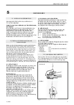
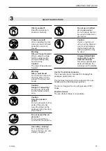
Page 15: ...s ten sioned The strap could break Caution Danger of squeezing Do not put your fingers into the tension wheel area Caution Only strap packed goods Do not put hands or other parts of the body bet ween...

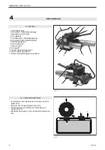
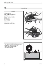
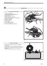
Page 16: ...straps Strap cut with knife 2 4 4 1 DESIGN 1 Suspension bow 2 Indicator welding cooling down 3 Strap guide 16 19 25 4 Base plate 5 Compressed air connection 6 Black button strap release 7 Gear housing...

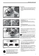
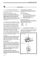
Page 17: ...eping the air line lubricator filled with oil and correctly adjusted Without proper lubrication the motor will become sticky and the tool will give low and erratic tension and be difficult to release...

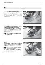
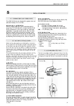
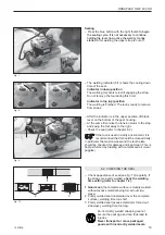
Page 18: ...up to the stop The beginning of the strap projects approx 5 cm 2 outside the front of the tool Release the tension motor The straps are now clamped and inserted in the tool 6 OPERATING INSTUCTIONS Fi...

Page 19: ...tly welded strapping cannot secure the package and can thus lead to injuries Never transport or move packaged goods with incorrectly welded seals The welding indicator 8 1 shows the cooling down time...

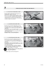
Page 20: ...1 4 the welding time will be longer by turning counter clock wise it will be shorter Adjust welding time according chapter 6 2 Fig 10 2 Replace the cap over the setting screw 7 PREVENTIVE AND CORRECT...

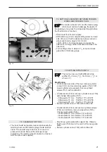
Page 21: ...out the dust wear eye protection The tension wheel can also be cleaned with the wire brush supplied 7 5 SETTING STRAP WIDTH The tool can be used with different strap widths 15 16 mm 5 8 18 19 mm 3 4 o...

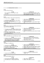
Page 22: ...pressure 4 Worn O ring pos 57 on main piston Fault Strap is over welded CAUSE 1 Improper weld timing adjustment Fault The cut off has become difficult CAUSE 1 Strap residue jamming cutter mechanism 2...

Page 23: ...tique 27 5 2 Installation de l alimentation en air 27 5 3 Suspension de l appareil 27 6 Mode d emploi 28 6 1 Mode d emploi pour l appareil 28 6 2 V rification du sertissage 29 7 Instruction de service...

Page 24: ...nent d importants renseignements savoir comment l appareil doit fonctionner en toute s curit selon les crit res professionnels et d une mani re conomique Les respecter aide viter les dangers diminuer...

Page 25: ...e car le feuillard peut se casser quand il est tendu Prudence danger d crasement Ne touchez pas la molette et l environnement avec les doigts Prudence cercler uniquement le paquet Ne mettez pas la mai...

Page 26: ...onner le feuillard aide du couteau 2 4 4 1 MODULES PRINCIPAUX 1 Archet suspension 2 Indicateur soudage refroidissement 3 Guide de bande 16 19 25 4 Plaque de base 5 Raccordement air comprim 6 Touche no...

Page 27: ...mentation d air comprim Un grand s parateur peut tre directement mont dans le circuit pneu matique mais cela n cessite une vidange quotidienne avant l utilisation de l outil b Lubrification Le moteur...

Page 28: ...on 30 cm de la main Saisir avec la main droite l appareil et relever le moteur jusqu la but e Pousser l appareil contre les feuillards jusqu la but e Le d but du feuillard doit ressortir d environ 5 c...

Page 29: ...ssi reux il est recommand de nettoyer l appareil r guli rement La molette de tension et la plaque dent e devraient tre tout particuli rement contr l es pour pr venir un ventuel endommagement et main t...

Page 30: ...8 dans le sens des aiguilles d une montre la dur e de soudage est plus importante dans le sens contraire elle est plus faible R gler la dur e de soudage d apr s le chapitre 6 2 illustration 10 2 Repla...

Page 31: ...et la matrice de tension Nettoyer par simple soufflage air comprim protections pour les yeux 7 5 R GLAGE DE LA LARGEUR DE BANDE L appareil peut utiliser largeurs de bandes diff rentes 15 16 mm 18 19 m...

Page 32: ...ante 4 Piston principal ou joint torique us s Probl me Soudure trop forte la bande se fissure dans le sertis sage CAUSES 1 La dur e de soudage est mal r gl e Probl me La coupe est devenue difficile CA...

Page 33: ...M6 x 16 Set screw Goujon fi let 1 20 1111 181 261 Passstift 5 x 10 Dowel pin Goujon 1 21 1111 259 935 Zylinderschraube M3 X 12 Cylinder screw Vis cylindrique 2 23 1111 276 191 Zylinderschraube M4 X 10...

Page 34: ...1 58 1111 423 924 Feder Spring Ressort 1 59 1111 423 925 Vibrator Arm Vibrator arm Bras vibrateur 1 60 1111 426 118 Seitenplatte Outer link B quille ext rieure 1 61 1111 423 932 Feder Spring Ressort 1...

Page 35: ...llager Bearing Roulement 1 92 1111 423 995 O ring O ring Anneau O 1 93 1111 423 996 Benzing Sicherungsring Retaining ring Circlip 2 94 1111 423 997 Nadellager Bearing Roulement 2 95 1111 423 999 Passs...

Page 36: ...4 125 1111 425 145 Nadellager Bearing Roulement 1 126 1111 425 137 Distanzring Spacer Anneau d cartement 1 127 1111 425 642 Schnecke Spiroid Spirale 1 128 1111 425 647 Distanzring Thrust ring Anneau...

Page 37: ...e mainte nance Disconnect tool from air supply D connecter l air comprim de l appareil avant chaque travail de maintenance ou de r paration Loctite 242 Loctite 609 OR P 400 WARNING Inspect all parts d...

Page 38: ...P 400 HD uivalent uivalent Loctite 242 Loctite 609 WARNING Inspect all parts daily and replace them if they are worn or broken Failure to do this can affect a product s operation and could result in...

Page 39: ...Seegerring Retaining ring Circlip 1 20 1111 424 162 Seegerring Retaining ring Circlip 1 21 1111 424 166 Gewindering Locking nut Ecrou de blocage 1 22 1111 023 547 Kugellager Ball bearing Roulement bi...

Page 40: ...O ring O ring Anneau O 2 39 1111 424 161 Kugellager Ball bearing Roulement bille 1 40 1111 014 541 Tellerfeder Belleville spring ressort disques 2 41 1111 422 870 Zahnkranz Ring gear Couronne du pign...

Page 41: ...P 400 HD Spannmotor Tension motor Moteur de tension WARNING Inspect all parts daily and replace them if they are worn or broken Failure to do this can affect a product s operation and could result in...

Page 42: ...derstift Spring pin Axe du ressort 2 11 1111 422 815 Zylinder Cylinder Cylindre 1 12 1111 424 154 Hintere Motorplatte Back end plate Flasque de recouvrement arri re 1 13 1111 424 161 Kugellager Ball b...

Page 43: ...400 HD Schweissmotor Welding motor Moteur de soudage WARNING Inspect all parts daily and replace them if they are worn or broken Failure to do this can affect a product s operation and could result i...

Reviews: