12.07/WE
21
ORGAPACK OR-P 400 HD
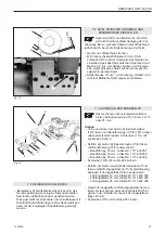
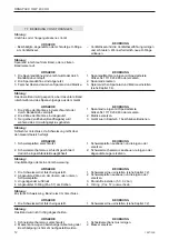
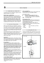
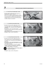
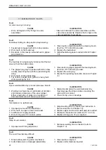
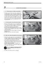
Fig. 14
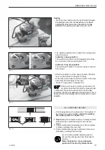
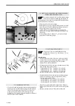
Fig. 15
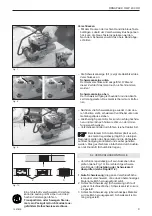
7.4 SETTING CLEARENCE BETWEEN TENSION
WHEEL AND TENSION PLUG
The tension wheel (14/1) and the tension plug
(14/2) must not touch (damage the teeth). If
the spacing is too great, the strap slips through before
the
fi
nal tension is reached.
– Disconnect tool from air supply.
– With Allen key (3 mm) adjust setting screw on lower
side of tool, so that the clearence between tension
wheel and tension plug is 0.2–0.4 mm
(.008“–.0016“). Turning clockwise increases the
clearence, turning counterclockwise decreases the
clearence.
– Turn setting screw in steps of
1
/
8
turns and check
gap with an thickness gauge.
0,1–0,2 mm
1
2
3
7.6 CLEANING THE TOOL
– The tool should be regulary cleaned. Especially the
tension wheel and the tension plug should be kept
clean. The easiest way to do this, is to use com-
pressed air and to blow out the dust (wear eye
protection). The tension wheel can also be cleaned
with the wire brush supplied.
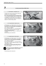
7.5 SETTING STRAP WIDTH
The tool can be used with different strap
widths
(15–16
mm
(
5
/
8
“), 18–19 mm (
3
/
4
“) or
25
mm
(1“).
Modi
fi
cation
– On front and rear side of the tool, remove cylinder
screw (15/1) and reverse strap guides (15/2) 180°,
mount cylinder screws again. Secure cylinder
screws (15/1) with Loctite 222.
– On lateral side of tool, remove cylinder screw (15/6)
and change strap guide (15/7):
– Strap guide 19 mm Part No 1111.423.957
– Strap guide 16 mm Part No 1111.423.956
– Strap guide 25 mm Part No 1111.424.394
– Secure cylinder screw (15/6) with Loctite 222.
– On lateral side of tool, remove two cylinder screws
(15/4) and uniformly remove support bar (15/5).
Change guide plate (15/9):
– Guide plate 19 mm Part No 1111.423.979
– Guide plate 16 mm Part No 1111.423.978
– Guide plate 25 mm Part No 1111.424.393
– Mount new guide plate with support bar. Observe
that the pin (15/3) lies in the notch of the new guide
plate.
– Secure cylinder screw (15/4) with Loctite 222.
1
2
1
2
4
5
6
7
8
9
3

