Installations Instructions
BDE Installation
OceanTRx™4-500 O3b System Installation Guide
3-5
3.3.1.2
Ship's Compass to CCU
Connect the
CCU COMPASS-NMEA
rear panel D-type (9-pin) connector to the ship's
NMEA compass
.
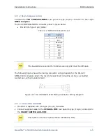
The CCU COMPASS-NMEA connector pinout is given below.
RS-422 (D-Type 9 pin) Cable:
Table
3-2: NMEA Connector Pin-out
Pin
Signal
1
Reserved
2
RX -
3
Reserved
4
RX +
5
GND
6
NC
7
NC
8
NC
9
GND
Pins 1 and 3 are reserved for internal use only and must be left open.
The following figure shows the mating connector wiring diagram for the RS-422
NMEA-0183 compass signal. The recommended interconnecting wiring is a shielded
twisted pair, with grounded shield.
Figure
3-3: RS-422 NMEA-0183 Mating Connector Wiring Diagram
3.3.1.3
CCU to OSS AUX COM
The OSS is supplied with a D-type (15-pin) flat cable.
Connect supplied cable to the
CCU AUX-COM
rear panel D-type (15-pin) connector to
the
OSS RF SWITCH AUX-COM
.
This cable is used for Triple Antenna Installation Only.


