


System Commissioning
Blockage Zones Configuration
OceanTRx™4-500 O3b System Installation Guide
4-17
4
4
.
.
5
5
B
B
l
l
o
o
c
c
k
k
a
a
g
g
e
e
Z
Z
o
o
n
n
e
e
s
s
C
C
o
o
n
n
f
f
i
i
g
g
u
u
r
r
a
a
t
t
i
i
o
o
n
n
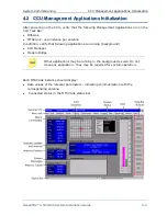
OceanTRx™4-500 allows inserting up to four blockage zone angles (per antenna). Each
zone is defined by the azimuth and elevation angles. In addition, the LNB power supply
(LNBV) can be turned ON or OFF globally for all defined zones.
For additional information on blockage zones configuration and antenna
behavior, refer to the OceanTRx™4-500 User Manual
.
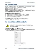
To configure the Blockage Zones
1. Using the MTSVLink, From the
Config
menu, select
Antenna Blockage
.
Figure
4-16: Blockage Zones configuration
2. For each blockage zone define the following:
Azimuth
(horizontal blockage range) - Azimuth angles relative to the ship’s bow-
to-stern axis.
Elevation
(vertical blockage range) - Elevation angles relative to the ship’s deck
level.
3. To disable LNB power supply when the antenna path comes across a blockage zones,
check
LNB Mute
.
4. Click
OK (Enter)
to close dialog.
5. Save by pressing
[V]
and
Enter
on the keyboard.


