


OSS
Element Descriptions
2-2
OceanTRx™4-500 O3b System Installation Guide
Table
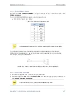
2-1: Relevant CCU Rear Panel Interfaces
Interface
Function
COMPASS NMEA
D-type 9-pin interface to an NMEA type compass.
NOTE: For compass type SYNCHRO or SBS, connect to the D-Type 25-
pin connector.
LAN Com (2 ports)
Ethernet ports for connection to the ship’s LAN
AUX COM
D-Type (15-pin). Dual-system, OSS connection.
USB (2 ports)
General purpose USB ports (e.g. can be used to connect a
mouse)
VGA
HD15. External video monitor connection.
Used in conjunction with keyboard and mouse (USB
connections) for direct management connection to the CCU.
POWER (inlet)
Male connector to mains AC power 115/230VAC
POWER (switch)
Power ON/OFF
GND
Ground lug
2
2
.
.
2
2
O
O
S
S
S
S
The Orbit System Selector (OSS) is an RF switch controlled by the CCU. It supports a
coax connection to a single antenna and (depending on the physical topology), can
provide RF switching functions between two or three L-band simplex inputs to the
satellite modem. The OSS operates in conjunction with the CCU. The OSS is connected to
the network; however, it is
managed by the CCU
.
Some tri-antenna system configurations require two OSS units.
For installations in which the modem does not supply the 10 MHz
signal in the UL, specific OSS models can generate the 10 MHz
signal to be multiplexed and transmitted along with the L-band
RF signal and the LAN (control) signal over a single coaxial cable
between the Antenna and the OSS.
OSS operation in the O3b system
When installed in the O3b system, the OSS provides RF switching for the L-band signals
between the BDE units (
Terminal
Rx 1/2/3 and Tx 1/2/3) and the Modem (
Modem
(Tx
and Rx-1/2).
In the UL, it splits the signal from the Modem (Modem Tx and 10 MHz) towards the
Terminal Tx ports to which the BDE units are connected.


