


Chapter 4
Servicing Motherboard Components
4-9
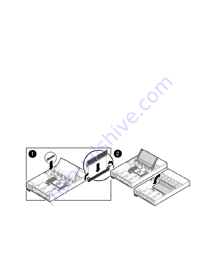
4. Push the DDR2 DIMM into the connector until the ejector tabs lock the DDR2
DIMM in place.
If the DDR2 DIMM does not easily seat into the connector, verify that the
orientation of the DDR2 DIMM is as shown in
FIGURE 4-5
. If the orientation is
reversed, damage to the DDR2 DIMM might occur.
5. Repeat
Step 2
through
Step 4
until all replacement DDR2 DIMMs are installed.
6. Replace the air duct to the down position.
7. Install the top cover.
See
Section 6.1, “Installing the Top Cover” on page 6-2
.
8. Slide the server into the rack.
See
Section 6.3, “Returning the Server to the Normal Rack Position” on page 6-4
.
9. Reconnect the power cord (or cords) to the power supply (or supplies).
Verify that the AC Present LED is lit.
See
Section 6.4, “Powering On the Server” on page 6-5
.
10. Power on the server.
See
Section 6.4, “Powering On the Server” on page 6-5
.
FIGURE 4-5
Installing DDR2 DIMMs
4.1.5
Installing Additional DDR2 DIMMs
Before you begin, see
Section 4.1.2, “DDR2 DIMM Guidelines” on page 4-4
, for
information about DDR2 DIMM configuration guidelines.
Summary of Contents for Sun Fire X4240
Page 1: ...Sun Fire X4240 Server Service Manual Part No 820 3835 14 September 2010 Revision A ...
Page 9: ...Contents ix Index Index 1 ...
Page 10: ...x Sun Fire X4240 Server Service Manual September 2010 ...
Page 39: ...Chapter 2 Preparing to Service the System 2 13 FIGURE 2 6 Removing the Top Cover ...
Page 40: ...2 14 Sun Fire X4240 Server Service Manual September 2010 ...
Page 76: ...4 14 Sun Fire X4240 Server Service Manual September 2010 FIGURE 4 7 Installing the Air Duct ...
Page 83: ...Chapter 4 Servicing Motherboard Components 4 21 FIGURE 4 11 Removing a PCIe Card ...
Page 140: ...5 30 Sun Fire X4240 Server Service Manual September 2010 ...


