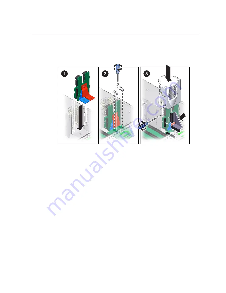
Install the PS Backplane
Ensure that the tabs on the power board slide onto the hooks on the power supply cage.
5.
Install the four bus bar screws to secure the mother board to the PS backplane
(panel 2).
Use a No. 2 Phillips screwdriver to tighten the bus bar screws until the PS backplane and the
motherboard are securely fastened to the bus bars.
6.
Replace the PS backplane cover (panel 3).
a.
Align the PS backplane cover.
Ensure that the tooth at the bottom of the cover is clear of the power supply cage.
You must guide two slots on the PS backplane cover around two pins on the inside of the
power supply cage.
b.
Fit the two slots on the cover around the two pins.
c.
Lift up the cover a little to guide the two pins into the other part of the slots.
d.
Attach the screw to fasten the PS backplane cover in place.
166
SPARC T5-2 Server Service Manual • February 2017
Summary of Contents for SPARC T5-2
Page 1: ...SPARC T5 2 Server Service Manual Part No E28856 13 February 2017 ...
Page 2: ......
Page 10: ...10 SPARC T5 2 Server Service Manual February 2017 ...
Page 12: ...12 SPARC T5 2 Server Service Manual February 2017 ...
Page 52: ...52 SPARC T5 2 Server Service Manual February 2017 ...
Page 96: ...96 SPARC T5 2 Server Service Manual February 2017 ...
Page 112: ...112 SPARC T5 2 Server Service Manual February 2017 ...
Page 120: ...120 SPARC T5 2 Server Service Manual February 2017 ...
Page 140: ...140 SPARC T5 2 Server Service Manual February 2017 ...
Page 156: ...156 SPARC T5 2 Server Service Manual February 2017 ...
Page 162: ...162 SPARC T5 2 Server Service Manual February 2017 ...
Page 174: ...174 SPARC T5 2 Server Service Manual February 2017 ...
Page 180: ...180 SPARC T5 2 Server Service Manual February 2017 ...
Page 185: ...Index SP 133 video connector location of 13 viewing message log files 50 185 ...
Page 186: ...186 SPARC T5 2 Server Service Manual February 2017 ...


