background image

-

84


7  Software CompactConnect 


Minimum system requirements: 


Windows 7, 8, 10 


USB interface 


Hard disc with at least 30 MByte of free space 


At least 128 MByte RAM 


CD-ROM drive 


A detailed description is provided in the software manual on the software CD. 


7.1  Installation 

1.  Insert the installation CD into the according drive on your computer. If the 

autorun


option

 is 

activated the installation wizard will start automatically. 
 

2.  Otherwise start 

CDsetup.exe

 from the CD-ROM. Follow the instructions of the wizard until the 

installation is finished.  


Summary of Contents for CTlaser 05M

Page 1: ...Operator s Manual optris CTlaser LT LTF 05M 1M 2M 3M MT F2 F6 G5 P7 Infrared thermometer...

Page 2: ...Optris GmbH Ferdinand Buisson Str 14 13127 Berlin Germany Tel 49 30 500 197 0 Fax 49 30 500 197 10 E mail info optris global Internet www optris global...

Page 3: ...e of contents 3 1 General Notes 9 1 1 Intended use 9 1 2 Warranty 10 1 3 Scope of delivery 10 1 4 Maintenance 11 1 5 Model Overview 12 2 Technical Data 14 2 1 Factory settings 14 2 2 General specifica...

Page 4: ...ment specifications 2M models 23 2 8 Measurement specifications 3M models 24 2 9 Measurement specifications 3M MT F2 models 25 2 10 Measurement specifications F2 F6 P7 models 26 2 11 Measurement speci...

Page 5: ...CoolingJacket Advanced 50 3 1 6 Outdoor protective housing 51 3 1 7 IR app Connector 52 4 Electrical Installation 53 4 1 Connection of the cables 53 4 2 Power supply 58 4 3 Cable assembling 58 4 4 Gro...

Page 6: ...Inputs 64 4 7 1 Analog outputs 64 4 7 2 Digital Interfaces 66 4 7 3 Relay outputs 67 4 7 4 Functional inputs 68 4 7 5 Alarms 69 5 Operation 72 5 1 Sensor setup 72 5 2 Aiming laser 79 5 3 Error messag...

Page 7: ...tocol 86 7 2 3 ASCII Protocol 87 7 2 4 Save parameter settings 88 8 Basics of Infrared Thermometry 89 9 Emissivity 90 9 1 Definition 90 9 2 Determination of unknown emissivity 91 9 3 Characteristic em...

Page 8: ...8 Appendix C Smart Averaging 96 Appendix D Declaration of Conformity 97...

Page 9: ...easurement spot on the object surface This lies within the two laser points The CTlaser sensing head is a sensitive optical system Please use only the thread for mechanical installation Avoid abrupt c...

Page 10: ...he warranty also expires if you open the product The manufacturer is not liable for consequential damage or in case of a non intended use of the product If a failure occurs during the warranty period...

Page 11: ...cles using clean compressed air The lens surface can be cleaned with a soft humid tissue moistened with water or a lens cleaner e g Purosol or B W Lens Cleaner Never use cleaning compounds which conta...

Page 12: ...05M 05M 1000 to 2000 C 0 525 m measurement of liquid metal CTlaser 1M 1ML 1MH 1MH1 485 to 1050 C 650 to 1800 C 800 to 2200 C 1 0 m metals and ceramic surfaces CTlaser 2M 2ML 2MH 2MH1 250 to 800 C 385...

Page 13: ...gases CTlaser G5 G5L G5H G5HF 100 to 1200 C 250 to 1650 C 200 to 1650 C 5 0 m measurement of glass CTlaser P7 P7 0 to 710 C 7 9 m plastic foils and surfaces of glass Table 1 Overview of models In the...

Page 14: ...ia software only Appendix C Smart Averaging Signal output object temperature 0 5 V Emissivity 0 970 LT LTF MT F2 F6 G5 P7 1 000 05M 1M 2M 3M Transmissivity 1 000 Average time AVG 0 2 s LT 0 1 s LTF MT...

Page 15: ...600 1000 1500 Lower alarm limit C Normally closed 30 1200 600 800 1200 350 500 800 100 250 350 550 Upper alarm limit C Normally open 100 1600 900 1400 1600 600 1200 1400 300 500 600 1000 Lower limit s...

Page 16: ...Lower alarm limit C Normally closed 750 400 600 400 600 400 600 200 350 350 30 Upper alarm limit C Normally open 1200 1200 1400 1200 1400 1200 1400 500 900 900 100 Lower limit signal output 0 V Upper...

Page 17: ...0 125 C 40 85 C Relative humidity 10 95 noncondensing Material Stainless steel Die casting zinc Dimensions 100 mm x 50 mm M48x1 5 89 mm x 70 mm x 30 mm Weight 600 g 420 g Cable length 3 m standard 8 m...

Page 18: ...er 635 nm 1 mW On Off via programming keys or software Outputs analog Channel 1 selectable 0 4 20 mA 0 5 10 V thermocouple J or K or alarm output Signal source object temperature Channel 2 LT LTF MT F...

Page 19: ...Profibus DP Ethernet optional plug in modules Relay outputs 2 x 60 VDC 42 VACRMS 0 4 A optically isolated optional plug in module Functional inputs F1 F3 software programmable for the following funct...

Page 20: ...at ambient temp 23 5 C 0 5 C or 0 5 1 C or 1 Temperature resolution NETD 0 1 K 0 5 K Response time 90 signal 120 ms 9 ms Warm up time 10 min Emissivity Gain Transmissivity 0 100 1 100 adjustable via...

Page 21: ...TMeas 1100 C 0 1 TMeas 1 C 1100 C Temperature resolution NETD 0 2 K Response time 2 90 signal 1 ms Emissivity Gain 0 100 1 100 adjustable via programming keys or software Transmissivity 0 100 1 000 ad...

Page 22: ...rature 23 5 C 0 1 TMeas 1 C Temperature resolution NETD 0 1 K Response time 2 90 signal 1 ms Emissivity Gain 0 100 1 100 adjustable via programming keys or software Transmissivity 0 100 1 000 adjustab...

Page 23: ...temperature 23 5 C 0 1 TMeas 1 C Temperature resolution NETD 0 1 K Response time 2 90 signal 1 ms Emissivity Gain 0 100 1 100 adjustable via programming keys or software Transmissivity 0 100 1 000 ad...

Page 24: ...mperature resolution NETD 0 1 K Response time 4 90 signal 1 ms Emissivity Gain 0 100 1 100 adjustable via programming keys or software Transmissivity 0 100 1 000 adjustable via programming keys or sof...

Page 25: ...or 0 5 C 2 Temperature resolution NETD 0 1 K Response time 90 signal 1 ms 3 10 ms Emissivity Gain 0 100 1 100 adjustable via programming keys or software Transmissivity 0 100 1 000 adjustable via prog...

Page 26: ...temperature 23 5 C 0 5 C or 0 5 2 Temperature resolution NETD 0 1 K 0 5 K Response time 90 signal 10 ms 150 ms Emissivity Gain 0 100 1 100 adjustable via programming keys or software Transmissivity 0...

Page 27: ...at ambient temperature 23 5 C 0 5 C or 0 5 Temperature resolution NETD 0 1 K Response time 90 signal 120 ms 80 ms 10 ms Emissivity Gain 0 100 1 100 adjustable via programming keys or software Transmi...

Page 28: ...calculator can also be used on the optris website http www optris com spot size calculator The size of the measuring object and the optical resolution of the infrared thermometer determine the maximum...

Page 29: ...Technical Data 29 LT Optics CF1 D S focus distance 75 1 0 9mm 70mm D S far field 3 5 1 LT Optics SF D S focus distance 75 1 16mm 1200mm D S far field 24 1...

Page 30: ...30 LT Optics CF2 D S focus distance 75 1 1 9mm 150mm D S far field 7 1 LT Optics CF3 D S focus distance 75 1 2 75mm 200mm D S far field 9 1...

Page 31: ...Technical Data 31 LT Optics CF4 D S focus distance 75 1 5 9mm 450mm D S far field 18 1 LTF Optics SF D S focus distance 50 1 24mm 1200mm D S far field 20 1...

Page 32: ...32 LTF Optics CF1 D S focus distance 50 1 1 4mm 70mm D S far field 3 5 1 LTF Optics CF2 D S focus distance 50 1 3mm 150mm D S far field 6 1...

Page 33: ...Technical Data 33 LTF Optics CF3 D S focus distance 50 1 4mm 200mm D S far field 8 1 LTF Optics CF4 D S focus distance 50 1 9mm 450mm D S far field 16 1...

Page 34: ...0mm D S far field 115 1 05M 1ML 2ML Optics FF D S focus distance 150 1 24mm 3600mm D S far field 84 1 1MH 1MH1 2MH 2MH1 3MH1 H3 Optics SF D S focus distance 300 1 3 7mm 1100mm D S far field 48 1 05M 1...

Page 35: ...0 1 0 5mm 150mm D S far field 7 5 1 1ML 2ML Optics CF2 D S focus distance 150 1 1mm 150mm D S far field 7 1 1MH 1MH1 2MH 2MH1 3MH1 H3 Optics CF3 D S focus distance 300 1 0 7mm 200mm D S far field 10 1...

Page 36: ...S focus distance 100 1 36mm 3600mm D S far field 65 1 1MH 1MH1 2MH 2MH1 3MH1 H3 Optics CF4 D S focus distance 300 1 1 5mm 450mm D S far field 22 1 1ML 2ML Optics CF4 D S focus distance 150 1 3mm 450mm...

Page 37: ...37 3ML Optics FF D S focus distance 60 1 60mm 3600mm D S far field 45 1 3MH Optics SF D S focus distance 100 1 11mm 1100mm D S far field 38 1 3ML Optics SF D S focus distance 60 1 18 3mm 1100mm D S f...

Page 38: ...0 1 0 85mm 85mm D S far field 4 1 3ML Optics CF1 D S focus distance 60 1 1 4mm 85mm D S far field 4 1 3MH Optics CF2 D S focus distance 100 1 1 5mm 150mm D S far field 7 1 3ML Optics CF2 D S focus dis...

Page 39: ...nce 100 1 2mm 200mm D S far field 9 1 3ML Optics CF3 D S focus distance 60 1 3 4mm 200mm D S far field 8 1 3MH Optics CF4 D S focus distance 100 1 4 5mm 450mm D S far field 19 1 3ML Optics CF4 D S foc...

Page 40: ...5 1 1 6mm 70mm D S far field 3 1 G5H Optics CF1 D S focus distance 70 1 1mm 70mm D S far field 3 4 1 MT MTH F2 F2H F6 F6H G5L G5HF P7 Optics SF D S focus distance 45 1 27mm 1200mm D S far field 25 1 G...

Page 41: ...ce 45 1 3 4mm 150mm D S far field 6 1 G5H Optics CF2 D S focus distance 70 1 2 2mm 150mm D S far field 6 8 1 MT MTH F2 F2H F6 F6H G5L G5HF P7 Optics CF3 D S focus distance 45 1 4 5mm 200mm D S far fie...

Page 42: ...42 MT MTH F2 F2H F6 F6H G5L G5HF P7 Optics CF4 D S focus distance 45 1 10mm 450mm D S far field 15 1 G5H Optics CF4 D S focus distance 70 1 6 5mm 450mm D S far field 17 7 1...

Page 43: ...d to the object activate the integrated double laser 5 2 Aiming laser The CTlaser is equipped with a metric M48x1 5 thread and can be installed either directly via the sensor thread or with help of th...

Page 44: ...44 Figure 2 Mounting bracket adjustable in one axis Order No ACCTLFB standard scope of supply...

Page 45: ...Mechanical Installation 45 Figure 3 Electronic box...

Page 46: ...ds on the application and the installation conditions on site The lens must be kept clean at all times from dust smoke fumes and other contaminants in order to avoid reading errors These effects can b...

Page 47: ...Mechanical Installation 47 3 1 2 Mounting bracket This adjustable mounting bracket allows an adjustment of the sensor head in two axes Figure 5 Mounting bracket adjustable in two axes Order No ACCTLAB...

Page 48: ...cations at higher ambient temperatures we recommend the usage of the optional water cooled housing operating temperature up to 175 C and the optional high temperature cable operating temperature up to...

Page 49: ...tallation 49 3 1 4 Rail mount adapter for electronic box With the rail mount adapter the CTlaser electronics can be mounted easily on a DIN rail TS35 according EN50022 Figure 7 Rail mount adapter Orde...

Page 50: ...or higher temperatures up to 180 C the CoolingJacket is provided for CTlaser Order No ACCTLCJ For even higher temperatures up to 315 C the CoolingJacket Advanced is provided for CTlaser Order No ACCTL...

Page 51: ...ed for outdoor applications by using the outdoor protective housing Order No ACCTLOPH24ZNS Figure 8 Outdoor protective housing for CTlaser LT with integrated heater incl prot window ZnS and air purge...

Page 52: ...e or tablet 6 IRmobile app The connector cable can be also used for the connection to your PC in combination with the software CompactConnect which can be downloaded for free under https www optris gl...

Page 53: ...of a standard CTlaser sensor into the connector version Order No ACCTLCONK Basic version The basic version is supplied with a connection cable connection sensing head electronics For the electrical i...

Page 54: ...riginal ready made fitting connection cables which are optionally available Consider the pin assignment of the connector see Figure 13 This version has a connector plug integrated in the sensor backpl...

Page 55: ...version only PIN Designation Wire color original sensor cable Figure 13 Connector plug exterior view 1 Detector signal Yellow 2 Temperature probe head Brown 3 Temperature probe head White 4 Detector...

Page 56: ...ound 0 V of internal in and outputs OUT AMB Analog output head temperature mV OUT TC Analog output thermocouple J or K OUT mV mA Analog output object temperature mV or mA F1 F3 Functional inputs AL2 A...

Page 57: ...er supply GND Ground 0 V of internal in and outputs AL2 Alarm 2 Open collector output OUT TC Analog output thermocouple J or K OUT mV mA Analog output object temperature mV or mA F1 F3 Functional inpu...

Page 58: ...and data lines use shielded cables only The sensor shield has to be grounded The cable gland M12x1 5 allows the use of cables with a diameter of 3 to 5 mm 1 Remove the isolation from the cable 40 mm p...

Page 59: ...fix the shield between two of the metal washers 4 Insert the cable into the cable gland until the limit stop and screw the cap tight Every single wire may be connected to the according screw clamps a...

Page 60: ...he ground connections GND power supply outputs are connected with the ground of the electronics housing To avoid ground loops and related signal interferences in industrial environments it might be ne...

Page 61: ...ion the ground connections GND power supply outputs are connected with the ground of the electronics housing To avoid ground loops and related signal interferences in industrial environments it might...

Page 62: ...ust be exchanged The sensing head is already connected to the electronics by factory default Inside a certain model group an exchange of sensing heads and electronics is possible Entering of the calib...

Page 63: ...gns of the first block With Up and Down each sign can be changed Mode switches to the next sign or next block Figure 19 Sensing head 4 6 Exchange of the head cable To avoid influences on the accuracy...

Page 64: ...to the head housing 4 7 Outputs and Inputs 4 7 1 Analog outputs The CTlaser has two analog output channels Consider that there are different connection pins on the mainboard OUT mV mA or OUT TC accor...

Page 65: ...OUT TC Thermocouple TC K OUT TC Output channel 2 on LT G5 P7 only The connection pin OUT AMB is used for output of the head temperature 20 180 C as 0 5 V or 0 10 V signal The CompactConnect software a...

Page 66: ...erface requires a minimum 12 V supply voltage Pay attention to the notes on the according interface manuals CTlaser sensors can be optionally equipped with an USB RS232 RS485 CAN Bus Profibus DP or Et...

Page 67: ...tching thresholds are in accordance with the values for alarm 1 and 2 4 7 5 Alarms The alarm values are set according to the 2 1 Factory settings For advanced settings change of low and high alarm a d...

Page 68: ...the hold functions F2 analog external emissivity adjustment 0 10 V 0 V 0 1 9 V 1 10 V 1 1 F3 analog external compensation of ambient temperature the range is scalable via software 0 10 V 40 900 C pre...

Page 69: ...nly To activate the according output channel has to be switched into digital mode For this purpose the software CompactConnect is required Visual alarms These alarms will cause a change of the color o...

Page 70: ...ition as low or high alarm via change of normally open closed selection of the signal source TObj THead TBox a digital interface e g USB RS232 including the software CompactConnect is needed Both alar...

Page 71: ...r output AL2 The transistor acts as a switch In case of alarm the contact is closed A load consumer Relay LED or a resistor must always be connected The alarm voltage here 24V must not be connected di...

Page 72: ...ly To set the CTlaser back to the factory default settings press at first the Down key and then the Mode key and keep both pressed for approx 3 seconds RESET appears as confirmation in the display The...

Page 73: ...infinite u 0 0 Lower limit temperature range 0 C depending on model inactive at TCJ and TCK output n 500 0 Upper limit temperature range 500 C depending on model inactive at TCJ and TCK output 0 00 Lo...

Page 74: ...ional optics e g is mounted between sensor and object The standard setting is 1 000 100 if no protective window etc is used A 0 2 Setup of Average time In this mode an arithmetic algorithm will be per...

Page 75: ...time This value will be held again for the specified time After this the signal will drop down with slow time constant and will follow the current object temperature V Setup of Valley hold If the valu...

Page 76: ...TActual without post processing u 0 0 Setup of the Lower limit of temperature range The minimum difference between lower and upper limit is 20 K If you set the lower limit to a value upper limit the u...

Page 77: ...g 0 5 V 5 00 Setup of the Upper limit of the signal output This setting allows an assignment of a certain signal output level to the upper limit of the temperature range The adjustment range correspon...

Page 78: ...ue will be taken from the head internal probe To return to XHEAD press Up and Down together M 01 Setup of the Multidrop address In a RS485 network each sensor will need a specific address This menu it...

Page 79: ...irect exposure via reflective surfaces The two laser points mark the position of the measuring spot but not its exact size The exact size of the measurement spot can be found in the optical charts 2 1...

Page 80: ...ure 22 Identification of the laser The laser can be activated deactivated via the programming keys on the unit or via the software If the laser is activated a yellow LED is shining beside temperature...

Page 81: ...oo low 0x No error CH Head temperature too high 1x Head temperature probe short circuit to GND vvvCH Head temperature too low 2x Box temperature too low 4x Box temperature too high 6x Box temperature...

Page 82: ...d analyse your infrared temperature measurement on a connected smartphone or tablet This app works on most Android devices running 4 4 or higher with a micro USB port supporting USB OTG On The Go It i...

Page 83: ...ing of 4 20 mA 0 10 V output and setup of alarm output Change of temperature unit Celsius or Fahrenheit Saving loading of configurations and T t diagrams Restore factory default sensor settings Integr...

Page 84: ...A detailed description is provided in the software manual on the software CD 7 1 Installation 1 Insert the installation CD into the according drive on your computer If the autorun option is activated...

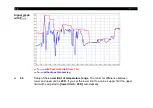
Page 85: ...all the software from your system use the uninstall icon in the start menu Figure 23 Software CompactConnect Main functions Graphic display for temperature trends and automatic data logging for analys...

Page 86: ...erial Interface Baud rate 9 6 115 2 kBaud adjustable on the unit or via software Data bits 8 Parity none Stop bits 1 Flow control off 7 2 2 Protocol All sensors of the CTlaser series are using a binar...

Page 87: ...Software CompactConnect 87 7 2 3 ASCII Protocol To switch to the ASCII protocol use the following command Decimal 131 HEX 0x83 Data Answer byte 1 Result 0 Binary protocol 1 ASCII protocol...

Page 88: ...nge continuously the flash mode can be switched off by using the following command Decimal 112 HEX 0x70 Data Answer byte 1 Result 0 Data will be written into the flash memory 1 Data will not be writte...

Page 89: ...ce temperature on the basis of the emitted infrared radiation from an object The most important feature of infrared thermometers is that they enable the user to measure objects contactless Consequentl...

Page 90: ...n emissivity of 1 0 whereas a mirror shows an emissivity of 0 1 If the emissivity chosen is too high the infrared thermometer may display a temperature value which is much lower than the real temperat...

Page 91: ...ity to 0 95 and take the temperature of the sticker Afterwards determine the temperature of the adjacent area on the measuring object and adjust the emissivity according to the value of the temperatur...

Page 92: ...able Appendix A and Appendix B These are average values only The actual emissivity of a material depends on the following factors temperature measuring angle geometry of the surface thickness of the m...

Page 93: ...ghened 0 05 0 2 0 05 0 2 0 05 0 15 0 05 0 1 oxidized 0 2 0 8 0 2 0 9 0 5 0 8 0 4 0 8 Chrome 0 4 0 4 0 03 0 3 0 02 0 2 Gold 0 3 0 01 0 1 0 01 0 1 0 01 0 1 Haynes alloy 0 5 0 9 0 6 0 9 0 3 0 8 0 3 0 8 I...

Page 94: ...3 0 1 0 15 0 05 0 15 oxidized 0 8 0 9 0 4 0 7 0 3 0 6 0 2 0 5 Platinum black 0 95 0 9 0 9 Silver 0 04 0 02 0 02 0 02 Steel polished plate 0 35 0 25 0 1 0 1 rustless 0 35 0 2 0 9 0 15 0 8 0 1 0 8 heavy...

Page 95: ...Carborundum 0 95 0 9 0 9 Ceramic 0 4 0 8 0 95 0 8 0 95 0 95 Concrete 0 65 0 9 0 9 0 95 Glass plate 0 2 0 98 0 85 melt 0 4 0 9 0 9 Grit 0 95 0 95 Gypsum 0 4 0 97 0 8 0 95 Ice 0 98 Limestone 0 4 0 98 0...

Page 96: ...verage function is that fast temperature peaks which are caused by dynamic events are subjected to the same averaging time Therefore those peaks can only be seen with a delay on the signal output The...

Page 97: ...Appendix D Declaration of Conformity 97 Appendix D Declaration of Conformity...

Page 98: ...optris CTlaser E2018 12 A...

Reviews: