Electrical Installation
55
-
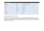
Pin assignment of connector plug (connector version only)
PIN
Designation
Wire color (original sensor cable)
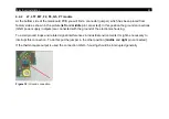
Figure 13:
Connector plug (exterior view)
1
Detector signal (+)
Yellow
2
Temperature probe head
Brown
3
Temperature probe head
White
4
Detector signal (–)
Green
5
Ground Laser (–)
Grey
6
Power supply Laser (+)
Pink
7
--
Not used
Summary of Contents for CTlaser 05M
Page 1: ...Operator s Manual optris CTlaser LT LTF 05M 1M 2M 3M MT F2 F6 G5 P7 Infrared thermometer...
Page 8: ...8 Appendix C Smart Averaging 96 Appendix D Declaration of Conformity 97...
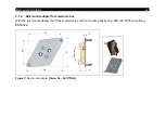
Page 44: ...44 Figure 2 Mounting bracket adjustable in one axis Order No ACCTLFB standard scope of supply...
Page 45: ...Mechanical Installation 45 Figure 3 Electronic box...
Page 97: ...Appendix D Declaration of Conformity 97 Appendix D Declaration of Conformity...
Page 98: ...optris CTlaser E2018 12 A...


