background image

OPTIMUM

M A S C H I N E N   -   G E R M A N Y

Version 1.0.1   2018-1-31

81

Originalbetriebsanleitung

TM4010  |  TM4010D

DE | GB

T

M

4010_

T

M

4010D_p

art

s.

fm

7.14

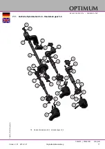
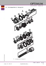
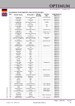
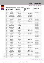
Vorschubgetriebe 3-6  - Feed gear 3-6

7-11:   Vorschubgetriebe 3-6 - Feed gear 3-6

A

65

66

67

68

69

64

70

1

2

3

4

6

3

5

5

7

8

9

10

11

12

7

7

14

15

16

17

18

19

Summary of Contents for OPTiturn TM 4010

Page 1: ...GB OPTIMUM M A S C H I N E N G E R M A N Y Operating Manual Version 1 0 1 Lathe Part no 3403040 3403045...

Page 2: ...witch 14 1 9 3 Protective cover with interlock switch 14 1 9 4 Lathe chuck protection with position switch 14 1 9 5 Chip guard shield 15 1 9 6 Prohibition warning and mandatory signs 15 1 10 Safety ch...

Page 3: ...Restoring readiness for operation 35 4 7 Momentary switch direct run 35 4 8 Speed setting 35 4 9 Turning direction 35 4 10 Feed 36 4 10 1 Feed speed 36 4 11 Tables for thread cutting 36 4 11 1 Metric...

Page 4: ...ering spare parts 67 7 2 Elektrische Ersatzteile Electrical spare parts 67 7 3 Schaltplan Wiring diagram 67 7 4 Maschinenbett Machine bed 68 7 5 Antrieb Steuerung Actuation control 70 7 6 Getriebe Spi...

Page 5: ...ight 112 9 2 Terminology Glossary 112 9 3 Change information manual 112 9 4 Liability claims warranty 113 9 5 Storage 114 9 6 Dismantling disassembling packing and loading 114 9 6 1 Decommissioning 11...

Page 6: ...operation as well as its long service life In the paragraph Maintenance all maintenance works and functional tests are described which the operator must perform in regular intervals The illustration...

Page 7: ...sary measures must be taken to comply with the country specific regula tions before commissioning the lathe Always keep this documentation close to the lathe If you would like to order another operati...

Page 8: ...er and its possible consequences 1 2 2 Pictograms Symbol Alarm expression Definition consequence DANGER Impending danger that will cause serious injury or death to people WARNING A danger that can cau...

Page 9: ...l danger of explosion If the lathe is used in any way other than described above or modified without the approval of Maschinen Germany GmbH then the lathe is being used improperly We will not be held...

Page 10: ...and tools e g emery cloth or files It is forbid den to use any hand tools on this machine The machine is not suitable for attachment kits for cylindrical grinding When mounting attachment kits for cyl...

Page 11: ...nnect the lathe when cleaning or maintenance work is being carried out WARNING The lathe may only be used with the safety devices activated Disconnect the lathe immediately whenever you detect a failu...

Page 12: ...thorized persons WARNING Inappropriate operation and maintenance of the lathe constitutes a danger for the personnel objects and the environment Only authorized personnel may operate the lathe Persons...

Page 13: ...ion unit CAUTION Risk of fire and explosion by using flammable materials or cooling lubricants Extra precautionary measures must be taken before machining flammable materials e g aluminium magnesium o...

Page 14: ...en the main switch is switched off the power supply to the machine is completely inter rupted WARNING Dangerous voltage even if the main switch is switched off The areas marked by the pictogram might...

Page 15: ...oils or other corrosive substances from the operator side can also lead to a deteri oration of the polycarbonate windows The result is a reduced retention capability of the poly carbonate viewing pan...

Page 16: ...ng the lathe ensure that this will neither endanger other persons nor cause damage to equipment Avoid any unsafe work methods Avoid any unsafe work methods Make sure that your work does not endanger a...

Page 17: ...horization and keep the key in a safe place All machine parts as well as all dangerous voltages are switched off Excepted are only the positions which are marked with the adjoining pictogram These pos...

Page 18: ...ure that the electrical systems and operating equipment are inspected with regards to their proper condition namely by a qualified electrician or under the supervision and direction of a qualified ele...

Page 19: ...OPTIMUM M A S C H I N E N G E R M A N Y Version 1 0 1 dated 2018 01 31 Page 19 Translation of the original instructions TM4010 TM4010D GB TM4010_TM4010D_GB_1 fm...

Page 20: ...machine bed mm 400 Swing diameter over cross slide mm 250 Main spindle bore mm 52 2 3 Headstock Main spindle nose DIN ISO 702 2 no 5 Camlock Reducing cone in the main spindle MT4 Main spindle morse t...

Page 21: ...uired or not The following factors influence the actual degree of the noise exposure of the operator Characteristics of the working area e g size of damping behaviour other noise sources e g the numbe...

Page 22: ...0_TM4010D_GB_2 fm This information about the noise emission should however allow the machine operator to eval uate the hazards and risks more easily CAUTION Depending on the total noise exposure and t...

Page 23: ...ated 2018 01 31 Page 23 Translation of the original instructions TM4010 TM4010D GB TM4010_TM4010D_GB_2 fm 2 13 Dimensions installation plan 100 200 1325 225 1850 481 331 669 766 1741 1462 135 687 837...

Page 24: ...eck immediately that it has not been damaged during transport Also check that no fastening screws have come loose Compare the scope of delivery with the attached packing list or the delivery note 3 3...

Page 25: ...oint 3 3 2 Gravity of the machine Dimensions installation plan on page 23 3 3 3 Lifting with a forklift Put two steel rods with a diameter of 30 to 34mm round steel C45 thick walled tube and a length...

Page 26: ...the lifting slings on the steel rods with clamping rings to prevent slip ping Firmly clamp the tailstock Slowly raise the machine using the crane 3 4 Installation and assembly 3 4 1 Installation site...

Page 27: ...ed e g by means of a sepa rate workplace lamp INFORMATION The main switch of the lathe must be freely accessible 3 5 Cleaning the machine CAUTION Do not use compressed air to clean the machine Your ne...

Page 28: ...ration dampers type SE2 part no 3381016 The 6 pcs SE1 vibration dampers are fixed on the 6 pcs 12mm through holes of the machine base The maximum height adjustment per element is 10mm Tighten the jack...

Page 29: ...dated 2018 01 31 Page 29 Translation of the original instructions TM4010 TM4010D GB TM4010_TM4010D_GB_3 fm Drawing Dimensions installation plan on page 23 A A B B Detail C A A B B C 100 150 DIN 529 M...

Page 30: ...e on the centre of the bed and using the four end adjusting screws 1 adjust until the machine spirit level displays an approximate value Move the carriage to the headstock and then to the tailstock an...

Page 31: ...ly use the tool clamping devices e g lathe chuck that were delivered with the machine or those offered by OPTIMUM as optional equipment Only use tool clamping devices in the intended admissible speed...

Page 32: ...ll become null and void if the machine is connected incorrectly 3 10 Warming up the machine ATTENTION If the lathe and in particular the lathe spindle are immediately operated at maximum load when col...

Page 33: ...on Pos Designation 1 Selector lever speed adjustment 2 Change wheel and feed table 3 Control panel 4 Selector lever feed gear 5 Chip sump 6 Lathe chuck protection 7 Chip guard shield 8 Machine lightin...

Page 34: ...l malfunctions rectified promptly Stop the lathe immediately in the event of any abnormality in operation and make sure it cannot be started up accidentally or without authorisation Notify the person...

Page 35: ...ck the emergency stop switch again Switch the control on 4 6 Power failure Restoring readiness for operation Set the rotational direction control lever to the neutral position Switch the control on 4...

Page 36: ...feed Example Feed 0 07 mm spindle revolution With the same settings you will achieve a longitu dinal feed of 0 261mm spindle revolution Set selection lever to A C R Install the change gears wheels ac...

Page 37: ...rs Loosen the clamping screw on the quadrant Slew the quadrant up Mount and position the change gears as indicated on the table Img 4 2 Change gears Example Loosen the screws of the change wheel b and...

Page 38: ...57 54 60 60 30 4 1 1 1 1 3 2 1 V V V V V V V V A D B D A B C C a b 4 5 5 6 6 7 A D B D A B C C a 4 9 8 9 10 11 12 13 14 16 20 18 22 26 28 24 19 32 36 48 38 40 44 56 52 Zollgewinde Wechselr der Hebel H...

Page 39: ...ool must be exactly aligned with the height of the lathe centre to obtain a shoulder free face The facing process is a turning operation in which the turning tool feeds perpendicular to the axis of ro...

Page 40: ...ISO 702 2 holding fixture CAUTION Regularly check the closed status of the clamp bolt INFORMATION Mark each workpiece holder for instance by a nick in order to facilitate the recover of the preci sion...

Page 41: ...n the lathe chuck itself Replacement lathe chucks must comply with EN 1550 standards The minimum distance to the machine bed must not be less than 25 mm WARNING Do not clamp any workpieces that exceed...

Page 42: ...en into account The permissible speeds can be determined in accordance with VDI Guideline 3106 Determin ing the permissible speed for lathe chucks jaw chucks This guideline also allows for the resid u...

Page 43: ...other chemicals We recommend the use of ALTEMP Q NB 50 by Klueber for the lubrication of the sliding sur faces and clamping fixture of the supplied lathe chucks You may optionally use a lubricant for...

Page 44: ...ith a drill chuck with countersinking tools 4 14 1 Cross adjustment of the tailstock The cross adjustment of the tailstock is used for turning long thin bodies Loosen the adjusting screws in the front...

Page 45: ...ctivating the automatic feed The cross feed for the depth of cut is achieved using the cross slide Img 4 9 Graphic Longitudinal turning 4 15 2 Face turning and recessing In the facing operation the to...

Page 46: ...the workpiece The driving bolt which is screwed into the flange for the lathe chuck transmits the torque to the lathe dog The fixed centre glides into the centre hole of the workpiece on the spindle n...

Page 47: ...he threading engaging lever must be engaged during the whole thread cutting process This does not apply to thread pitches that can be carried out with the thread gauge The thread is produced in variou...

Page 48: ...distributors Make sure that the cooling agent is properly retrieved Respect the environment when dispos ing of lubricants and coolants Follow the manufacturer s disposal instructions 4 16 1 Cooling l...

Page 49: ...d and rotating workpiece Ensure the chuck s axial and concentric runout Check options for remedying imbalances on workpieces Reduce the speed Wear hearing protection If the chuck is involved in a coll...

Page 50: ...ipping from the outside inwards and with increasing RPM the effective clamping force is reduced by the magnitude of the increasing centrifugal force the forces are opposed When the RPM limit is exceed...

Page 51: ...e required tensioning force for processing a workpiece the centrifugal force of the clamping jaws must be taken into account The permissible speeds can be determined in accordance with VDI Guideline 3...

Page 52: ...the following also applies here The total centrifugal force Fc is dependent both on the sum of the masses of all jaws and on the center of gravity radius and the RPM ATTENTION For safety reasons in a...

Page 53: ...moment for one jaw The lathe chuck has 3 jaws Calculation of the total centrifugal force at a rotational speed of 2000 rpm The total possible clamping force of the chuck at a standstill is s 31 kN at...

Page 54: ...r and seizing Depending on the chuck type and operating state the tensioning force of a lathe chuck can decrease by up to 50 percent of the nominal tensioning force A presumably securely clamped workp...

Page 55: ...ttle cutting speeds result in cost efficient chipping 5 2 Influences on the cutting speed vc Cutting speed in m min t Service life in min The service life t is the period of time in minutes during whi...

Page 56: ...53 50 50 47 5 45 45 42 5 40 33 5 33 5 31 5 Rust resistant steel 600 700 P 10 80 75 71 71 67 63 56 53 50 50 47 5 45 45 42 5 40 33 5 33 5 31 5 31 5 30 28 Tool steel 1500 1800 High speed steel 9 7 5 6 5...

Page 57: ...serious injuries to those working on the lathe and damage to the lathe Only qualified personnel should carry out maintenance and repair work on the lathe Electrical systems and operating materials ma...

Page 58: ...nds to a large extent on the individual usage and operating conditions Any indicated intervals therefore are only valid for the corresponding approved con ditions Interval Where What How Start of work...

Page 59: ...fm When necessary Slideways Readjust Excessive clearance in the slideways can be reduced by read justing the tapered gibs Turn the take up screw clockwise The tapered gib is moved to the rear and redu...

Page 60: ...air work Feed gear Apron Headstock Visual inspec tion Check the oil level in the inspection glass of the feed gear of the apron of the headstock The oil level must at least attain the centre resp top...

Page 61: ...se an appropriate collecting container with sufficient capacity Unscrew the screw from the drain hole Unscrew the screw from the filler hole Close the drain hole if no more oil drains Fill up to the m...

Page 62: ...essary V belt check re tighten Exchange of the V belt set Open the side protective cover Loosen the clamping nuts of the motor plate Lift the motor plate to the top This will relax the V belt set Exch...

Page 63: ...ron Oiling Lubricate all oiler cups with machine oil do not use grease guns or the like weekly Lathe saddle Cross slide Top slide Lead screw Feed rod Tailstock at least annually Cooling lubricant syst...

Page 64: ...bricant should withstand the coolant and other chemicals Numerous different lathe chucks are available on the market which distinguish themselves con siderably based on the lubricating method Follow t...

Page 65: ...more than 10 6 ml there is an increase in nitrite content to more than 20 ppm mg 1 or nitrate content to more than 50 ppm mg 1 there is an increase in the N nitrosodiethanolamine NDELA to more than 5...

Page 66: ...creases 0 5 based on initial filing Measures in accordance manufacturer s rec ommendations 1 0 based on initial filing Replace cooling lubricant clean cooling lubri cant circulation system Usage conce...

Page 67: ...chines name Herstellungsdatum Date of manufacture Artikelnummer Article no Die Artikelnummer befindet sich in der Ersatzteilliste The article no is located in the spare parts list Die Seriennummer bef...

Page 68: ...on 1 0 1 2018 1 31 68 Originalbetriebsanleitung TM4010 TM4010D DE GB TM4010_TM4010D_parts fm 7 4 Maschinenbett Machine bed 7 1 Maschinenbett Machine bed 1 2 3 4 5 6 7 8 9 10 11 12 13 14 15 16 17 18 19...

Page 69: ...key 1 034030401310 11 Riemenscheibe Pulley 1 034030401311 12 Motorplatte Motor plate 1 034030401312 13 Welle Shaft 1 034030401313 14 L fter Fan 1 034030401314 15 Motorabdeckung Motor cover 1 03403040...

Page 70: ...A S C H I N E N G E R M A N Y Version 1 0 1 2018 1 31 70 Originalbetriebsanleitung TM4010 TM4010D DE GB TM4010_TM4010D_parts fm 7 5 Antrieb Steuerung Actuation control 7 2 Antrieb Steuerung Actuation...

Page 71: ...gelstift Taper pin 2 GB117 86 5x60 38 Manschette Sleeve 1 39 Innensechskant Justier schraube Socket head set screw 1 GB77 85 M6x8 42 Zugspindel Feed rod 1 03402050842 43 Positionseinstellstift Positio...

Page 72: ...A N Y Version 1 0 1 2018 1 31 72 Originalbetriebsanleitung TM4010 TM4010D DE GB TM4010_TM4010D_parts fm 7 6 Getriebe Spindelstock 1 6 Headstock gear 1 6 7 3 Getriebe Spindelstock 1 6 Headstock gear 1...

Page 73: ...A N Y Version 1 0 1 2018 1 31 73 Originalbetriebsanleitung TM4010 TM4010D DE GB TM4010_TM4010D_parts fm 7 7 Getriebe Spindelstock 2 6 Headstock gear 2 6 7 4 Getriebe Spindelstock 2 6 Headstock gear 2...

Page 74: ...010 TM4010D DE GB TM4010_TM4010D_parts fm 7 8 Getriebe Spindelstock 3 6 Headstock gear 3 6 7 5 Getriebe Spindelstock 3 6 Headstock gear 3 6 187 182 180 187 176 178 177 179 190 188 189 217 192 193 194...

Page 75: ...iginalbetriebsanleitung TM4010 TM4010D DE GB TM4010_TM4010D_parts fm 7 9 Getriebe Spindelstock 4 6 Headstock gear 4 6 7 6 Getriebe Spindelstock 4 6 Headstock gear 4 6 238 237 235 234 232 231 229 228 2...

Page 76: ...lbetriebsanleitung TM4010 TM4010D DE GB TM4010_TM4010D_parts fm 7 10 Getriebe Spindelstock 5 6 Headstock gear 5 6 7 7 Getriebe Spindelstock 5 6 Headstock gear 5 6 245 167 246 247 246 167 243 244 168 2...

Page 77: ...TM4010 TM4010D DE GB TM4010_TM4010D_parts fm 7 11 Getriebe Spindelstock 6 6 Headstock gear 6 6 7 8 Getriebe Spindelstock 6 6 Headstock gear 6 6 118 118 159 133 159 159 165 133 294 294 133 297 297 297...

Page 78: ...ngsring Retaining ring 1 DIN 471 35x1 5 042SR35W 196 Kugellager Bearing ring 1 6203 0406203R 197 Welle Shaft 1 03402050197 198 Gewindestift Grub screw 1 GB 80 85 M8 x 16 199 O Ring O Ring 1 DIN 3771 3...

Page 79: ...1 03402050267 294 Flansch Flange 2 034020501294 297 O Ring O ring 3 034020501297 299 Zahnrad Gear 1 034020501201299 300 Welle Shaft 1 034020501300 301 Schaltklaue Shifting claw 1 034020501301 302 Plat...

Page 80: ...ebsanleitung TM4010 TM4010D DE GB TM4010_TM4010D_parts fm 7 12 Vorschubgetriebe 1 6 Feed gear 1 6 7 9 Vorschubgetriebe 1 6 Feed gear 1 6 7 13 Vorschubgetriebe 2 6 Feed gear 2 6 7 10 Vorschubgetriebe 2...

Page 81: ...1 0 1 2018 1 31 81 Originalbetriebsanleitung TM4010 TM4010D DE GB TM4010_TM4010D_parts fm 7 14 Vorschubgetriebe 3 6 Feed gear 3 6 7 11 Vorschubgetriebe 3 6 Feed gear 3 6 A 65 66 67 68 69 64 70 1 2 3...

Page 82: ...on 1 0 1 2018 1 31 82 Originalbetriebsanleitung TM4010 TM4010D DE GB TM4010_TM4010D_parts fm 7 15 Vorschubgetriebe 4 6 Feed gear 4 6 7 12 Vorschubgetriebe 4 6 Feed gear 4 6 B 17 23 22 5 62 63 58 57 56...

Page 83: ...on 1 0 1 2018 1 31 83 Originalbetriebsanleitung TM4010 TM4010D DE GB TM4010_TM4010D_parts fm 7 16 Vorschubgetriebe 5 6 Feed gear 5 6 7 13 Vorschubgetriebe 5 6 Feed gear 5 6 C 17 23 22 5 61 7 7 7 43 8...

Page 84: ...nleitung TM4010 TM4010D DE GB TM4010_TM4010D_parts fm 7 17 Vorschubgetriebe 6 6 Feed gear 6 6 7 14 Vorschubgetriebe 6 6 Feed gear 6 6 D E F G 90 90 81 81 81 81 82 82 82 82 44 46 45 47 50 51 49 54 52 5...

Page 85: ...ing Cover 1 03400923326 27 Abstandst ck Spacer 1 03400923327 28 Abdeckung Cover 1 03400923328 34 Zahnrad Gear 1 03400923334 35 Abstandst ck Spacer 1 03400923335 36 Zahnrad Gear 1 03400923336 37 Zahnra...

Page 86: ...itzelwelle Pinion shaft 4 03400923382 85 lschauglas Oil Glass from 1 03403110385 90 Federstift Spring pin 4 GB879 86 5x40 03400923390 92 Feder Spring 4 GB2089 80 1x5x20 03400923392 93 Stahlkugel Steel...

Page 87: ...Change gear b 1 M1 25x39 0340304004839Z Wechselzahnrad b Change gear b 1 M1 25x54 0340304004854Z Wechselzahnrad b Change gear b 1 M1 25x57 0340304004857Z Wechselzahnrad b Change gear b 1 M1 25x60 0340...

Page 88: ...albetriebsanleitung TM4010 TM4010D DE GB TM4010_TM4010D_parts fm 7 19 Schlosskasten 1 3 Apron 1 3 7 16 Schlosskasten 1 3 Apron 1 3 A B C D E F 460 459 461 462 451 561 483 488 490 489 464 561 485 491 4...

Page 89: ...1 31 89 Originalbetriebsanleitung TM4010 TM4010D DE GB TM4010_TM4010D_parts fm 7 20 Schlosskasten 2 3 Apron 2 3 7 17 Schlosskasten 2 3 Apron 2 3 502 501 503 504 505 506 507 572 573 511 510 513 514 515...

Page 90: ...iginalbetriebsanleitung TM4010 TM4010D DE GB TM4010_TM4010D_parts fm 7 21 Schlosskasten 3 3 Apron 3 3 7 18 Schlosskasten 3 3 Apron 3 3 534 535 536 537 538 516 517 518 521 519 520 514 522 523 456 455 4...

Page 91: ...03401000477 478 Gewindestift Grub screw 1 GB 80 85 M6 x 6 03401000478 481 Spannstift Spring pin 2 GB 879 86 5 x 20 482 Abdeckplatte Cover 1 03401000482 483 Gewindestift Grub screw 5 GB 70 85 M6 x 12...

Page 92: ...et screw 1 M6 x 6 533 Schaltgabel Switching fork 1 03401000533 534 Innensechskantschraube Socket head screw 2 GB 70 85 M5 x 12 03401000534 535 Welle Shaft 1 03401000535 536 Zahnrad Gear 1 03401000536...

Page 93: ..._TM4010D_parts fm 7 22 Planschlitten Cross slide 7 19 Planschlitten cross slide 604 603 602 626 605 606 607 606 611 612 643 651 645 630 637 632 633 634 631 641 640 650 649 642 641 650 643 644 645 638...

Page 94: ...1 31 94 Originalbetriebsanleitung TM4010 TM4010D DE GB TM4010_TM4010D_parts fm 7 23 Oberschlitten Top slide 7 20 Oberschlitten Top slide 661 620 665 686 623 668 666 667 670 669 671 672 673 674 675 67...

Page 95: ...ew 4 GB 70 85 N8x40 638 Nachstellleiste Gib 2 03401000638 639 F hrungsschiene Guide rail 1 03401000639 640 F hrungsplatte Guide plate 1 03401000640 641 Sechskantschraube Hexagon screw 4 GB 5783 86 M8...

Page 96: ...Clamping nut 1 03402050669 695 Gewindestift Grub screw 1 M5x6 03402050669 696 Buchse Bushing 1 03402050669 697 Skalenring Scale ring 1 03402050669 698 RIng Ring 1 03402050669 699 Handhebel Handle 1 03...

Page 97: ...GB TM4010_TM4010D_parts fm 7 24 Reitstock Tailstock 7 21 Reitstock Tailstock 741 723 701 702 718 717 713 754 710 705 707 706 709 742 708 705 703 709 704 727 724 725 711 712 719 720 740 722 726 738 73...

Page 98: ...724 Reitstockk rper Housing 1 03401000724 725 Gewindestift Grub screw 1 GB 80 85 M6 x 6 726 Niet Rivet 4 727 Exzenter Excenter 1 03401000727 728 Griff Handle 2 03401000728 729 Hebel Lever 1 034010007...

Page 99: ...1 0 1 2018 1 31 99 Originalbetriebsanleitung TM4010 TM4010D DE GB TM4010_TM4010D_parts fm 7 25 Feststehehde L nette Steady rest 7 22 Feststehende L nette Steady rest 802 801 804 803 805 806 808 818 8...

Page 100: ...7 Mutter Nut 1 03401000807 808 feststehende L nette Ober teil Steady rest upper section 1 03401000808 809 Sechskantmutter Hexagon nut 4 GB 6170 86 M6 03401000809 810 Gewindestift Grub screw 3 GB 79 85...

Page 101: ...401000826 827 Gewindestift Grub Screw 2 GB 119 86 C 3 x 18 03401000827 828 berwurfmutter Sleeve nut 2 03401000828 829 Gewindestange Threaded rod 2 03401000829 830 Zentrierh lse Centering bushing 2 034...

Page 102: ...034030401103 4 Buchse Bushing 3 034030401104 5 Lager Bearing 3 034030401105 6 Aufnahme Collet 1 034030401106 7 Ring Ring 1 034030401107 8 Buchse Bushing 3 034030401108 9 Schalter Switch 1 034030401109...

Page 103: ...401205 6 Schutzglass Safety glass 1 034030401206 7 Scheibe Washer 10 5 8 Schraube Screw 4 M5 9 Platte Plate 1 034030401209 10 Klemmplatte Clamping plate 1 034030401210 11 Schraube Screw 2 M5 12 Sechsk...

Page 104: ...s scale 1 034020601404 5 Befestigung Glasme stab Fixing glass scale 1 034020601405 6 Befestigung Lesekopf Glasme stab Reading head mounting glass scale 1 034020601406 7 Glasme stab Planschlitten Glass...

Page 105: ...TIMUM M A S C H I N E N G E R M A N Y Version 1 0 1 2018 1 31 105 Originalbetriebsanleitung TM4010 TM4010D DE GB TM4010_TM4010D_parts fm 7 30 Schaltplan Wiring diagram 1 3 7 26 Schaltplan Wiring diagr...

Page 106: ...TIMUM M A S C H I N E N G E R M A N Y Version 1 0 1 2018 1 31 106 Originalbetriebsanleitung TM4010 TM4010D DE GB TM4010_TM4010D_parts fm 7 31 Schaltplan Wiring diagram 2 3 7 27 Schaltplan Wiring diagr...

Page 107: ...TIMUM M A S C H I N E N G E R M A N Y Version 1 0 1 2018 1 31 107 Originalbetriebsanleitung TM4010 TM4010D DE GB TM4010_TM4010D_parts fm 7 32 Schaltplan Wiring diagram 3 3 7 28 Schaltplan Wiring diagr...

Page 108: ...elay 2K7 Steuerelais Control relay 2Q2 Sicherungsautomat Automatical fuse 1 DELIXY DZ47S C6A 034030402Q2 2S5 Not Halt Schalter Emergency stop button 2 CE4T 10R 02 034030401320 2S5 1 2S5 2 Schalter Dre...

Page 109: ...Meropa 150 VG 100 CLP 100 Aral Degol BG 100 BP Energol GR XP 100 SPARTAN EP 100 Kl beroil GEM 1 100 Mobilgear 627 Shell Omala 100 Meropa 100 VG 68 CLP 68 Aral Degol BG 68 BP Energol GR XP 68 SPARTAN...

Page 110: ...pour broches haute vitesse VG 68 Deol BG 68 Emergol HLP D68 Spartan EP 68 Druck l KLP 68 C Shell Omala 68 Fett f r Zentralschmierung Flie fett Grease for central lubrica tion Graisse pour lubrificati...

Page 111: ...h V belt wear down V belt tension is too loose V belt check re tighten on page 62 Workpiece becomes conical Centre are not aligned tailstock offset Top slide is not exactly set to zero when turning wi...

Page 112: ...the feed gear and the synchronous belt pulleys Lead screw nut Split nut which engages the lead screw Lathe chuck Clamping tool for holding the workpiece Drill chuck Drill bit adapter Lathe saddle Slid...

Page 113: ...warranty claims Using the product beyond the technical options and proper use in particular due to over straining of the machine Any defects arising by one s own fault due to faulty operations or if t...

Page 114: ...nicipal waste manage ment If appropriate call on the help of a specialist waste disposal company for the treatment of the material Please make sure that electrical components are disposed of professio...

Page 115: ...hine with tensioning belts on the machine bed 9 7 Disposal of new device packaging All used packaging materials and packaging aids from the machine are recyclable and gener ally need to be supplied to...

Page 116: ...of this product will protect the environment and the public health Incorrect disposal constitutes a risk to the environment and public health Recycling of material will help reduce the consumption of...

Page 117: ...ntrolled lathe without numerical control The following other EU Directives have been applied EMC Directive 2014 30 EC The following harmonized standards were applied EN ISO 23125 2015 Machine tools Sa...

Page 118: ...nspection 57 Inspection deadlines 18 Installation site requirements 26 L Lathe chuck 49 Lathe spindle fixture 40 Lifting Crane 25 Forklift 25 Longitudinal turning 45 Lubrication 27 M Main switch 14 Ma...

Reviews: