OPTIMUM
M A S C H I N E N - G E R M A N Y
Version 1.0.1 dated 2018-01-31
Page 40
Translation of the original instructions
TM4010 | TM4010D
GB
T
M
4010_
T
M
4010D_G
B_4
.f
m
4.13
Lathe spindle fixture
WARNING!
Do not clamp any workpieces that exceed the permitted chucking capacity of the lathe
chuck. The clamping force of the chuck is too low if its capacity is being exceeded. The
clamping jaws may loosen.
Only use lathe chucks designed for the speed of the machine.
Do not use lathe chucks with an external diameter that is too large.
Please ensure that lathe chucks are manufactured to EN 1550 standards.
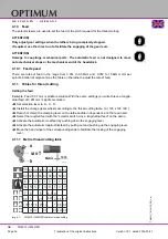
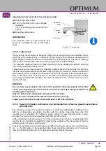
The spindle nose is designed as a Camlock 5 DIN ISO 702-2 holding fixture.
CAUTION!
Regularly check the closed status of the clamp bolt.
INFORMATION
Mark each workpiece holder for instance by a nick in order to facilitate the recover of the preci-
sion of the concentric run and the axial run-out deviation.
4.13.1 Fasten workpiece holder
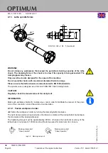
Fasten the workpiece holder by turning the clamping bolts clockwise.
The right clamp position is reached when the reference marker at the clamp holder are between
the two marks at the lead spindle seat.
The tightening torque must be approximately 80 Nm, otherwise the rotational accuracy of the
lathe chuck is not present. 100 Nm is about the torque used for aluminium rims on cars.
Img.4-6: Marking clamp bolt
13
8
2
,5
6
3
Ø
P
52
DIN ISO 702-2 Nr. 5 (Camlock)
7
°
7
´
3
0
´´
R
52
,40
6
x
60
°
P
19,80
Marking clamp bolt
"Open position"
Marking clamp bolt
"Closed position"
V
V
V
V


