OPTIMUM
M A S C H I N E N - G E R M A N Y
Version 1.0.1 dated 2018-01-31
Page 28
Translation of the original instructions
TM4010 | TM4010D
GB
T
M
4010_
T
M
4010D_G
B_3
.f
m
3.6
Anchor-free assembly
INFORMATION
Vibration dampers are not included in the scope of delivery.
ATTENTION!
Insufficient rigidity of the ground leads to superposition of vibrations between the lathe
and the ground (natural frequency of the components). Critical speeds with unpleasant
vibrations are rapidly achieved if the rigidity of the whole system is insufficient; this will
lead to bad turning results.
Attaching a solid surface at each contact point between the foundation and machine base or
use of vibration dampers type SE2, part no. 3381016 The 6 pcs. SE1 vibration dampers are
fixed on the 6 pcs. 12mm through holes of the machine base. The maximum height adjustment
per element is 10mm. Tighten the jackscrew, the vibration damper lifts up.
3.6.1
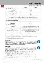
Dimension of vibration damper
3.6.2
Anchored assembly
INFORMATION
Anchor bolts and flat bars are not included.
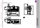
Core drillings are carried out on a light foundation with a diameter of 100mm and a depth of
150mm.
Lift the machine from the ground and center the machine in the inner holes with the anchor
bolts.
Place the underlay plates under the set screws.
Align roughly the machine.
Fill the drill holes with concrete and allow it to set.
Align the machine with the levelling screws and tighten the anchor bolts.
A
B [mm]
C [mm]
D [mm]
E [mm]
SE1
M12
70
10
32
120
SE2
M16
90
12
35
160
SE3
M20
130
12
40
185
Jackscrew
Counternut
A
B
C
D
E


