5-5
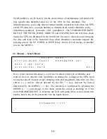
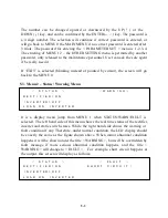
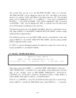
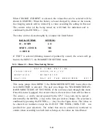
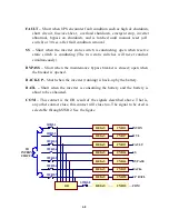
It is a select menu jump from MENU 1 when the REAL TIME DATA is selected.
The cursor (
→
) is used to select what type of real time data the user what to view,
such as RECTIFIER DATA, RESERVE DATA, OUTPUT DATA, OTHER DATA
etc. The cursor (
→
) can be moved upward by the UP (
↑
) key, and can be moved
downward by the DOWN (
↓
) key. The selection is confirmed by pressing the
ENTER (
←┘
), and change to the menu which the cursor is pointing at.
If ‘EXIT’ is selected (blinking instead of pointed by cursor), the screen will go
back to the MENU 1- the SELECT MENU.
5.5. Menu 4 – Historical Event Menu
<
D A T E
/
T I M E
/
E V E N T S
>
R U N : 2 1 Y R 0 3 M O
2 0 0 0 \ 0 3 \ 2 9
0 9 : 3 2
S H O R T
C I R C U I T
!
2 0 0 0 \ 1 2 \ 0 1
2 2 : 1 5
S H O R T
C I R C U I T
!
2 0 0 1 \ 0 1 \ 1 0
1 5 : 4 7
H I G H
D C
S H U N T D O W N
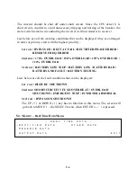
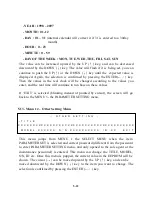
It is a display menu jump from MENU 1 when HISTORICAL DATA is selected.
The records stored in EEPROM when abnormal events happened are displayed in
this menu. The record display is started with the date and time stamped when the
abnormal condition happened. Therefore, it is possible for the user or
maintenance personnel to trace back what happen to the UPS in the past. 77
records can be stored in one EEPROM, can be increased to 154 records with 2
EEPROMs. All these records will not be erased by cutting off of the power supply
or complete shutdown of the UPS, i.e. they will be kept in EEPROM forever
except over written by the 78th (or the 155th) records.
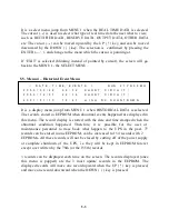
3 records can be displayed each time on the screen. The records displayed (once
this menu is popped) are the 3 most update records in the EEPROM. The
displayed records will move one record upward when the UP (
↑
) key is pressed,
and move one record downward when the DOWN (
↓
) key is pressed.
Summary of Contents for DS-D33
Page 1: ...OPTI UPS User s Guide Durable Series Models DS D33 www opti ups com ...
Page 16: ...1 12 1 7 Dimension Drawings 20KVA 60KVA OUTLINE DRAWING ...
Page 17: ...1 13 20KVA 60KVA INTERIOR DRAWING ...
Page 18: ...1 14 80KVA 160KVA OUTLINE DRAWING ...
Page 19: ...1 15 80KVA 160KVA INTERIOR DRAWING ...
Page 20: ...1 16 200KVA 320KVA OUTLINE DRAWING ...
Page 21: ...1 17 200KVA 320KVA INTERIOR DRAWING ...
Page 22: ...1 18 INTER PCB DIAGRAM ...

