5-7
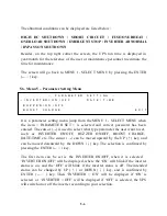
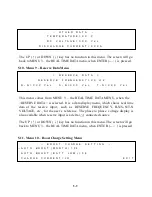
The second item can be set is the BUZZER ON/OFF, when it is selected
‘BUZZER ON/OFF’ will be displayed, where the ‘ON’ will blink if the buzzer
status is on, and the ‘OFF’ will blink if the buzzer status is off. The intended
status can be changed by UP (
↑
) or DOWN (
↓
) key, and is confirmed by
ENTER (
←┘
) key. Then ‘BUZZER = ON’ will be displayed if ‘ON’ is selected
or ‘BUZZER = OFF’ will be displayed if ‘OFF’ is selected, the UPS will switch
on or off the buzzer according to your selection.
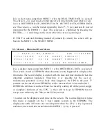
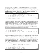
The third item can be set is the BOOST CHARGE, when it is selected the screen
will jump to MENU 10 the BOOST CHARGE SETTING MENU, and the setting
method will be explained later.
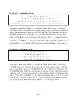
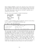
The forth item can be set is the DATE/TIME, when it is selected the screen will
jump to MENU 11 the DATE TIME SETTING MENU, and the setting method
will be explained in that section.
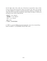
If ‘EXIT’ is selected (blinking instead of pointed by cursor), the screen will go
back to the MENU 1- the SELECT MENU.
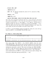
5.7. Menu 6 – Rectifier Data Menu
<
R E C T I F I E R
D A T A
>
R E C T I F I E R
F R E Q U E N C Y = X X
H Z
R - N = X X X
V a c
S - N = X X X
V a c
T - N = X X X
V a c
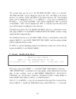
This menu comes from MENU 3 – the REAL TIME DATA MENU, when the
<RECTIFIER DATA> is selected. It is a data display menu which shows real time
data of the rectifier, such as RECTIFIER FREQUENCY, R-N/S-N/T-N
VOLTAGE, etc., for the user’s reference. The phase to phase voltage display is
also available when input is a delta (
△
) connected source.
The UP (
↑
) or DOWN (
↓
) key has no function in this menu. The screen will go
back to MENU 3 – the REAL TIME DATA menu, when ENTER (
←┘
) is pressed.
Summary of Contents for DS-D33
Page 1: ...OPTI UPS User s Guide Durable Series Models DS D33 www opti ups com ...
Page 16: ...1 12 1 7 Dimension Drawings 20KVA 60KVA OUTLINE DRAWING ...
Page 17: ...1 13 20KVA 60KVA INTERIOR DRAWING ...
Page 18: ...1 14 80KVA 160KVA OUTLINE DRAWING ...
Page 19: ...1 15 80KVA 160KVA INTERIOR DRAWING ...
Page 20: ...1 16 200KVA 320KVA OUTLINE DRAWING ...
Page 21: ...1 17 200KVA 320KVA INTERIOR DRAWING ...
Page 22: ...1 18 INTER PCB DIAGRAM ...

