


5-2
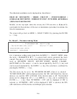
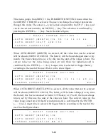
Serial number is set by factory for the convenience of maintenance personnel who
may need to take down the serial no. of the UPS he has attended. The
identification no. is set only when external module connect to more than one UPS,
each UPS must have a unique number to identify itself, and it should be set by
installation technical personnel after installation. The YEAR/MONTH/DATE,
DAY OF THE WEEK, HOUR: MINUTE and AM (PM) from the real time clock
inside the UPS are displayed in the fourth row for user’s reference and stamping
the date and time in the historical data when abnormal conditions happen. By
pressing one of the UP, DOWN or ENTER key, the LCD will change to another
screen, the MENU 1.
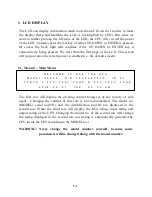
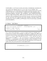
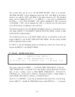
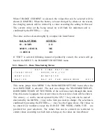
5.2. Menu 1 – Select Menu
<
S E L E C T
M E N U
>
→
S T A T U S
/
W A R N
/
F A U L T
P A R A M E T E R
S E T
R E A L
T I M E
D A T A
H I S T O R I C A L
D A T A
E X I T
It is a select menu with cursor (
→
) for user to select what type of data the user
what to view or may the user would like to change the settings of the UPS, such
as inverter on/off, buzzer on/off, charging time and magnitude, date/time etc. The
cursor (
→
) can be moved upward by the UP(
↑
) key, and can be moved
downward by the DOWN(
↓
) key. The selection is confirmed by pressing the
ENTER (
←┘
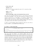
), and change to the menu which the cursor is pointing at. If the
item ‘PARAMETER SET’ is selected, the LCD will jump into a screen which will
ask the user to key in the password. See the figure below.
P A S S W O R D : 1 2 3 4
Summary of Contents for DS-D33
Page 1: ...OPTI UPS User s Guide Durable Series Models DS D33 www opti ups com ...
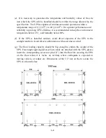
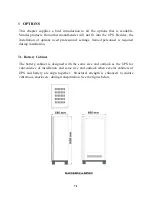
Page 16: ...1 12 1 7 Dimension Drawings 20KVA 60KVA OUTLINE DRAWING ...
Page 17: ...1 13 20KVA 60KVA INTERIOR DRAWING ...
Page 18: ...1 14 80KVA 160KVA OUTLINE DRAWING ...
Page 19: ...1 15 80KVA 160KVA INTERIOR DRAWING ...
Page 20: ...1 16 200KVA 320KVA OUTLINE DRAWING ...
Page 21: ...1 17 200KVA 320KVA INTERIOR DRAWING ...
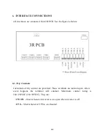
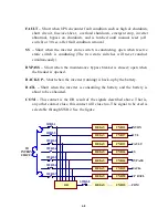
Page 22: ...1 18 INTER PCB DIAGRAM ...


