5-3
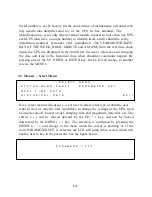
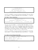
The number can be changed upward or downward by the UP(
↑
) or the
DOWN(
↓
) key, and can be confirmed by the ENTER(
←┘
) key. The password is
a 4 digit number. The selection will continue if correct password is entered, or
will go back to MENU 0 the MAIN MENU if no correct password is entered after
3 trials. The password for entering the < PARAMETER SET > menu is 1-2-3-4.
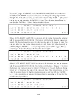
The entering of MENU 12 – the OTHER SETTING menu is permitted by another
password, only released to the maintenance personnel. User can ask the sole agent
if he really need it.
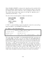
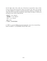
If ‘EXIT’ is selected (blinking instead of pointed by cursor), the screen will go
back to the MENU 0.
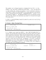
5.3. Menu 2 – Status / Warning Menu
<
S T A T U S
>
<
W A R N I N G
>
R E C T I F I E R = O N
I N V E R T E R = O F F
L O A D
O N
I N V E R T E R
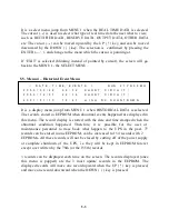
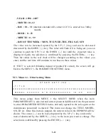
It is a display menu jump from MENU 1 when STATUS/WARN/FAULT is
selected. The left hand side of this menu shows the real time status of the rectifier,
inverter and static switch states. While the right hand side shows the warning or
fault condition if any. Therefore, under normal condition, the LCD display should
be exactly the same as the figure shown above. When minor abnormal condition
happens it will be shown under the title < WARNING >, but will be overridden by
fault message if more serious abnormal condition happens, and the title <
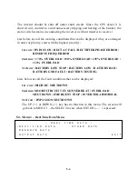
WARNING > will change to < FAULT >. For example, short circuit happens at
the output, this screen will display as follows:
<
S T A T U S
>
<
F A U L T
>
R E C T I F I E R = O N
S H O R T
C I R C U I T
!
I N V E R T E R = O F F
L O A D
O N
I N V E R T E R
Summary of Contents for DS-D33
Page 1: ...OPTI UPS User s Guide Durable Series Models DS D33 www opti ups com ...
Page 16: ...1 12 1 7 Dimension Drawings 20KVA 60KVA OUTLINE DRAWING ...
Page 17: ...1 13 20KVA 60KVA INTERIOR DRAWING ...
Page 18: ...1 14 80KVA 160KVA OUTLINE DRAWING ...
Page 19: ...1 15 80KVA 160KVA INTERIOR DRAWING ...
Page 20: ...1 16 200KVA 320KVA OUTLINE DRAWING ...
Page 21: ...1 17 200KVA 320KVA INTERIOR DRAWING ...
Page 22: ...1 18 INTER PCB DIAGRAM ...

