4-4
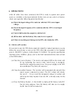
(b) Open the battery breaker – You have to shutdown the power inside the UPS;
therefore, continue to open the battery breaker.
(c) Open the rectifier breaker – Open the rectifier breaker will then further
take the power source away from the DC bus; therefore, the DC
bus will start to drop slowly. After 5 min., the DC bus will drop to
a safe level (let say 20VDC).
(d) Close the bypass breaker – Now the reserve breaker and reserve static
switch is still conducting, therefore when maintenance bypass
breaker is closed, power will flow through the bypass loop instead
of the reserve loop because the impedance of bypass loop is lower.
(e) Open the reserve breaker – You can now open the reserve breaker to free
the UPS from any power supply.
4.4. From Bypass to Inverter Procedure
If the UPS is in maintenance bypass mode, and you want to turn the UPS to
normal mode without interrupting the output AC, please follow the steps below.
(But this procedure is for standard system, 380/220V 3 phases 4 wires Input,
10~160KVA. For special specification and those above 160KVA, please refer to
the brief instruction label stuck in front of the PCB holder.)
(a) Close the reserve breaker – The reserve and output LED on the mimic will
lit up, indicating the reserve static switch loop is energized,
therefore the output has power now. The power supply in the UPS
also established. The fans will rotate too.
(b) Open the bypass breaker – The inverter cannot be switched on with the
maintenance bypass breaker is closed (because the CPU will
sense the breaker and prevent the inverter to connect directly to
AC source). And the reserve breaker has already closed, therefore
power goes through the reserve loop if bypass breaker is open, AC
at output will not be interrupted.
Summary of Contents for DS-D33
Page 1: ...OPTI UPS User s Guide Durable Series Models DS D33 www opti ups com ...
Page 16: ...1 12 1 7 Dimension Drawings 20KVA 60KVA OUTLINE DRAWING ...
Page 17: ...1 13 20KVA 60KVA INTERIOR DRAWING ...
Page 18: ...1 14 80KVA 160KVA OUTLINE DRAWING ...
Page 19: ...1 15 80KVA 160KVA INTERIOR DRAWING ...
Page 20: ...1 16 200KVA 320KVA OUTLINE DRAWING ...
Page 21: ...1 17 200KVA 320KVA INTERIOR DRAWING ...
Page 22: ...1 18 INTER PCB DIAGRAM ...

