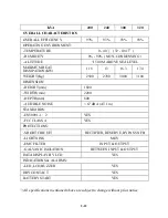


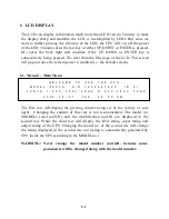
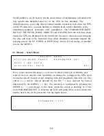
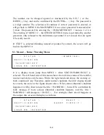
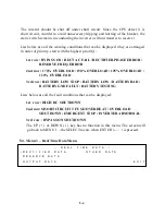

4-5
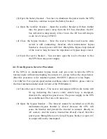
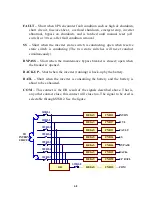
(c) Close the rectifier breaker - The rectifier will be automatically started if the
power source connected is correct. The DC voltage will slowly
rise up (15 – 30sec.) until the designated voltage is reached, and
will keep the value anyhow. Now, the DC is already ready for the
inverter.
(d) Close the battery breaker - A fuse holder is employed in the battery to the
DC bus for safety purpose. Now the batteries will take-over to
supply the DC bus if rectifier mains fail.
(e) Push inverter on switch – To on the inverter, the inverter on switch and the
control switch must be pressed simultaneously. The inverter will
start working and inverter output will be established in 4 sec. The
load will be automatically transferred to the inverter 3 sec. later.
Now the UPS comes again into normal operation now.
Summary of Contents for DS-D33
Page 1: ...OPTI UPS User s Guide Durable Series Models DS D33 www opti ups com ...
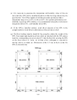
Page 16: ...1 12 1 7 Dimension Drawings 20KVA 60KVA OUTLINE DRAWING ...
Page 17: ...1 13 20KVA 60KVA INTERIOR DRAWING ...
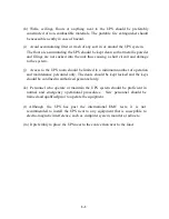
Page 18: ...1 14 80KVA 160KVA OUTLINE DRAWING ...
Page 19: ...1 15 80KVA 160KVA INTERIOR DRAWING ...
Page 20: ...1 16 200KVA 320KVA OUTLINE DRAWING ...
Page 21: ...1 17 200KVA 320KVA INTERIOR DRAWING ...
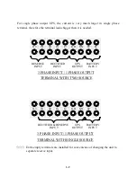
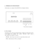
Page 22: ...1 18 INTER PCB DIAGRAM ...


