


74
Beginning Transfer Num-
ber
word n+2, bits 15-08
Set an integer between 00 and 25.
This number indicates the position where the first transfer is to be made. The
designated number of transfers will be transferred continuously from this
point.
See Appendix C DM Area Allocations for the words transferred with each
transfer number.
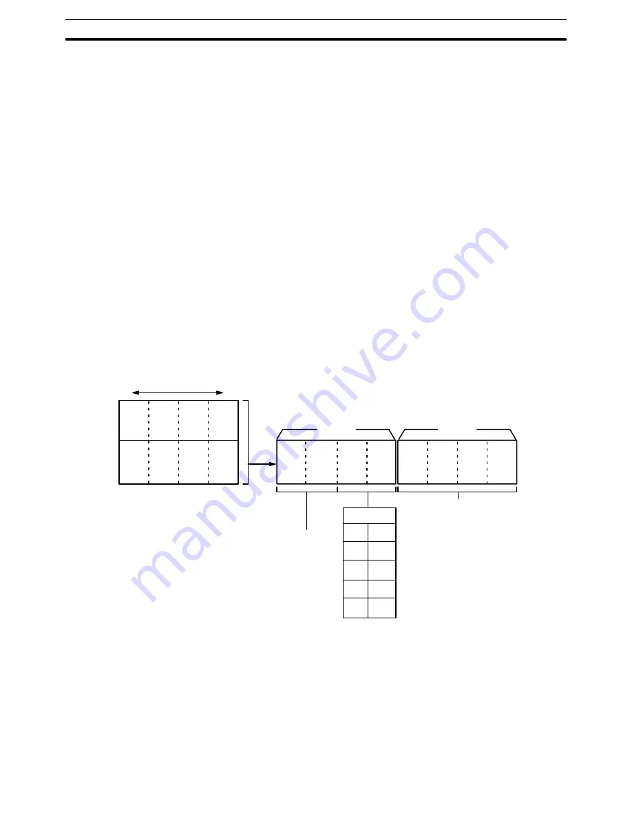
Beginning Word
Number
word n+3, bits 15-00
This is the first word in the PC data area that is to be transferred into the Po-
sition Control Unit beginning at the transfer number designated above. The
beginning word and ending word (computed from the number of transfers)
must be within one of the data areas designated during data preparation.
(See Data Preparation under 4–8–1 Normal Transfer.)
PC Data Area
word n+4, bits 07-00
Set the data area (in four digits BCD) from which the transfer is to be made.
15 00
Data Area
00
01
02
03
04
n+3
n+4
n+4
n+3
x10
3
x10
2
x10
1
x10
0
x10
1
x10
0
x10
1
x10
0
DM
I/O
LR
HR
AR
Beginning word number
Set a word
number in
4-digit BCD
code
Number of transfers
Number of Transfers
word n+4, bits 15-08
Set an integer between 01 and 26.
TRANSFER DATA
Command Bit
word n, bit 10
After the above settings are made, TRANSFER DATA is executed with this
bit. This can all be done in one scan.
Transfer Data
Section 4–8


