background image

7-2

7-1

Notes on Using Inverter for Motor

H

Using Inverter for Existing Standard Motor

When a standard motor is operated with this Inverter, a power loss is slightly higher than
when operated with a commercial power supply.

In addition, cooling effects also decline in the low-speed range, resulting in an increase
in the motor temperature. Therefore, motor torque should be reduced in the low speed
range.

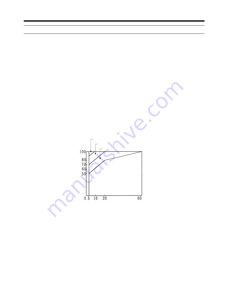
The figure on the right-hand side shows allowable load characteristics of a standard
motor.

If 100% torque is continuously required in the low-speed range, use a special motor for
use with Inverters.

Allowable Load Characteristics of Standard Motor

25% ED (or 15 minutes)

40% ED (or 20 minutes)

60% ED (or 40 minutes)

Continuous

Frequency (Hz)

T

orque (%)

D

High-speed Operation

When using the motor at a high speed (60 Hz or more), note that problems may arise in
dynamic balance, bearing durability, and so on.

D

Torque Characteristics

When the motor is operated with the Inverter, torque characteristics differ from when
operated with a commercial power supply. Check the load torque characteristics of the
machine to be used with the motor.

Appendix A

Chapter 7

Summary of Contents for SYSDRIVE 3G3EV SERIES

Page 1: ...USER S MANUAL SYSDRIVE 3G3EV Standard Models Compact Low noise Inverter Cat No I011 E1 3...

Page 2: ...to open the cover under any circumstances Doing so may result in injury or death and may damage the product Never attempt to repair or dis assemble the product 4 We recommend that you add the followin...

Page 3: ...4 2 4 2 Using the Digital Operator 4 3 4 2 1 Name and Function of Each Component 4 3 4 2 2 Outline of Operation 4 5 4 2 3 Setting Constants 4 8 4 3 Test Run 4 25 4 3 1 Checking Wiring 4 25 4 3 2 Turn...

Page 4: ...rns 5 11 5 2 7 Controller Receives Noise when Inverter is Started 5 11 5 2 8 AM Radio Receives Noise when Inverter is Started 5 11 5 2 9 Ground Fault Interrupter is Actuated when Inverter is Started 5...

Page 5: ...Chapter 1 Getting Started 1 1 Items to be Checked when Unpacking 1 2 Precautions 1...

Page 6: ...ter model Input specifications Output specifications D Checking the Model 3G3EV A2002M E Special Specification Specifications Maximum applicable motor capacity Voltage class Installation type Series n...

Page 7: ...cessory provided with the 3G3EV Standard Model Set screws and other necessary parts must be prepared by customers 1 2 Precautions To ensure safe operation of the 3G3EV note the following items H Alway...

Page 8: ...ectrical shock and damage the equipment H Do Not Modify Wiring or Check Signals When the Main Circuit is On Always turn the main circuit off before modifying wiring or checking signals Touching termin...

Page 9: ...Chapter 2 Overview 2 1 Features 2 2 Component Names 2...

Page 10: ...have been minimized to enable even first time users to set constants easily H Easy to Install D Very Small and Lightweight The 3G3EV Inverter is approximately half the size of our Low noise General p...

Page 11: ...n run using control terminals with a one touch operation D Checking a Test Run with Various Monitors Output frequency output current and the direction of motor rotation appear in the dis play section...

Page 12: ...als Run indicator Alarm indicator Control circuit terminals output Ground terminal Main Circuit Terminals Output Motor output terminals Digital Operator Control circuit terminals input MA MB MC SF SR...

Page 13: ...Monitor item indicators In service item indicators green indicators These items can be monitored or set even during operation Stopped item indicators red indicators These items can be set only when t...

Page 14: ...Chapter 3 Design 3 1 Installation 3 2 Wiring 3...

Page 15: ...kW Three phase 200 VAC Input H 3G3EV AB001 j to 3G3EV AB002 j 0 1 to 0 2 kW Single Three phase 200 VAC Input 4 5 dia Note 1 For the 3G3EV A2001 j 3G3EV A2002 j and 3G3EV AB001 j a U shaped notch 4 5...

Page 16: ...ree phase200 VAC Input Model 3G3EV model Output W H D W1 H1 T Weight kg AB001 j 0 1 kW 68 128 75 56 118 3 Approx 0 5 AB002 j 0 2 kW 108 3 Approx 0 6 H 3G3EV A2007 j to 3G3EV A2015 j 0 75 to 1 5 kW Thr...

Page 17: ...0 96 118 Approx 1 3 AB007 j 0 75 kW Approx 1 3 AB015 j 1 5 kW 130 170 118 Approx 2 0 D Three phase 400 VAC Input Model 3G3EV model Output W H D W1 H1 Weight kg A4002 j 0 2 kW 108 128 92 96 118 Approx...

Page 18: ...0 mm min 100 mm min Air Side Air Inverter Inverter Inverter H Ambient Temperature Control To enhance operation reliability the Inverter should be installed in an environment free from extreme temperat...

Page 19: ...erminals Braking resistor connection terminals Control circuit terminals output Ground terminal Main circuit terminals output Motor Output Terminals Output Control circuit terminals input MA MB MC SF...

Page 20: ...wiring When connecting a braking resistor always remove the resin plates with a pair of long nose pliers D Output Terminals Bottom Section Terminal symbol Name and description U V W Motor output termi...

Page 21: ...t common Input terminal common to SF SR and S1 FS Frequency reference power supply Output voltage 12 VDC Permissible amperage 20 mA FR Frequency reference input see note 2 0 to 10 VDC is input Input i...

Page 22: ...No 09 n09 is used to set the function This constant is factory set to operation in progress H Standard Connection Diagram Molded case circuit breaker MCCB Forward Stop Reverse Stop Multi function inpu...

Page 23: ...sed For the main circuit and ground always use 600 V polyvinyl chloride PVC cables If the cable is long and may cause voltage drops increase the wire size according to the cable length Model Terminal...

Page 24: ...uency countermeasures for Inverter D Installing a Magnetic Contactor This Inverter can be used without a magnetic contactor MC on the power supply side If the power supply for the main circuit is to b...

Page 25: ...eds the Inverter capacity overvoltage will be detected in the main circuit In such a case use a Braking Resistor or Braking Resistor Unit Note Be sure to create a sequence that will turn OFF the Inver...

Page 26: ...e a special purpose noise filter for Inverters Wiring Example 2 3G3EV General purpose noise filter Power supply SYSMAC etc Other controllers 3G3EV Power supply General purpose noise filter SYSMAC etc...

Page 27: ...ctromagnetic switch or magnetic contactor to the output circuit If a load is connected to the Inverter during operation an inrush current will actuate the overcurrent protective circuit in the Inverte...

Page 28: ...a grounded metal pipe to prevent induction noise Keeping the metal pipe at least 30 cm away from the signal line considerably reduces induction noise 3G3EV 30 cm min MCCB Metal pipe Power supply Signa...

Page 29: ...y n37 10 kHz max 1 2 3 4 5 kHz max 1 2 H Ground Wiring Always use a ground terminal with the following ground resistance 200 VAC Class 100 or less 400 VAC Class 10 or less For 400 VAC class models tha...

Page 30: ...5 to 0 75 mm2 D Wiring Method Wire each terminal as follows a Loosen the terminal screw with a thin slotted screwdriver b Insert the wire from underneath the terminal block c Tighten the terminal scre...

Page 31: ...bles from the main circuit cables and other power cables Connect the shield to the ground terminal of the Inverter Do not connect to the control ler Insulate the shield with tape to prevent it from co...

Page 32: ...Chapter 4 Preparing for Operation 4 1 Preparation Procedure 4 2 Using the Digital Operator 4 3 Test Run 4...

Page 33: ...ower voltage must be as follows single phase 200 to 240 VAC 50 60 Hz use terminals R and S Check that the motor output terminals U V and W and motor are connected cor rectly Check that the control cir...

Page 34: ...to run If any error has occurred refer to Section 5 Operation 4 2 Using the Digital Operator 4 2 1 Name and Function of Each Component H Name of Each Component Display section Operation keys Mode Key...

Page 35: ...only when the Inverter is stopped In this display the direction of motor rotation is displayed during operation D Operation Keys Mode Key Press this key to switch between monitor item indicators and...

Page 36: ...n the FOUT or IOUT indicator is lit the same indicator lights up next time the power is turned on Otherwise the FREF indicator always lights up Example of data display Indicator Description Reference...

Page 37: ...tion time seconds Deceleration time seconds Forward Reverse rotation selection f r Forward rotation reU Reverse rotation Maximum frequency Hz Maximum voltage V Maximum voltage frequency Hz Electronic...

Page 38: ...lue effective current A is displayed Note 1 The direction of rotation can be always monitored during operation The indica tors in the lower two rows of the display section flash indicating the directi...

Page 39: ...hanging acceleration time from 10 seconds to 50 seconds Key operation Indicator Example of data display Explanation 10 0 Press the Mode Key until the ACC indicator lights up Flashing 10 1 Press the In...

Page 40: ...e to 2 by pressing the Increment Key The data display section flashes indicating that the value is yet to be registered 2 Press the Enter Key The data display section stops flashing n02 After approxim...

Page 41: ...te 1 200 V see note 1 n26 Maximum voltage frequency 1 6 to 400 60 0 Hz n31 Electronic thermal reference current 0 0 to see note 2 See note 2 n33 Stall prevention during de celeration 0 1 0 n36 Operati...

Page 42: ...ng range 0 10 to 2 00 Setting range 0 10 to 2 55 n61 No Yes Yes n64 No No Yes Note Yes indicates that the constant can be set No indicates that the constant cannot be set H Details of Each Constant n0...

Page 43: ...setting 0 This constant is used to specify whether the Inverter is to be operated with a Digital Operator or external signals Value Run command Frequency reference DIP switch setting 0 Digital Operat...

Page 44: ...pressed or the operation command is OFF Value Description 0 Frequency deceleration stop 1 Free running Example of Frequency Deceleration Stop Output frequency Forward rotation Reverse rotation Operat...

Page 45: ...tor n06 Multi Function Input Selection Setting range 0 to 4 Factory setting 1 One of the following values can be selected for the multi function input S1 function Value Description 0 Forward reverse r...

Page 46: ...nce frequency and the output frequency falls within 2 Hz MA is turned off when the difference exceeds 4 Hz Example of Operation Output frequency Frequency matching for MA Detection range 2 Hz Referenc...

Page 47: ...e Key first press the Increment or Decrement Key to change the value then press the Enter Key If one of values 2 to 5 is set in n02 operation mode selection the n11 setting is disre garded and control...

Page 48: ...100 to 999 seconds 1 second Acceleration and deceleration times can be changed even during operation If for ex ample acceleration time is to changed light the ACC indicator with the Mode Key first pre...

Page 49: ...e The values in parentheses are for the 400 VAC class These three constants are used to set a V f pattern Check the motor specifications and set each constant as follows n24 Maximum frequency or rated...

Page 50: ...current of the maximum applicable motor n33 Stall Prevention during Deceleration Setting range 0 1 Factory setting 0 This constant is used to select the action to prevent overvoltage during decelerat...

Page 51: ...ion of Speed Search Function Motor speed Free running state Inverter starts operating Time n37 Carrier Frequency Setting range 1 2 3 4 see note 1 Factory setting 4 10 kHz see note 2 This constant is u...

Page 52: ...onstant so that the continuous output current does not exceed the val ues shown in the following tables 400 VAC Inverters of 0 75 kW or Less Carrier frequency set value Max continuous output current 1...

Page 53: ...ing to the maxi mum frequency n24 as a multiple of 10 V Frequency reference bias n40 Specify the reference frequency corresponding to in put voltage 0 V as a percentage of the maximum frequency n24 Ex...

Page 54: ...d Setting range 0 1 Factory setting 0 Used for setting the frequency from the Digital Operator Select the Enter Key operation when setting the frequency command from the Digital Operator Value Descrip...

Page 55: ...Description Error category c Overcurrent OC Errors that actuate protective U Main circuit overvoltage OV mechanism uU1 Main circuit undervoltage UV1 uU2 Control power supply fault UV2 h Radiation fin...

Page 56: ...ase input is only applicable to 3G3EV ABjjj 400 VAC Class Three phase input 380 to 460 VAC 50 60 Hz Check that terminals U V and W are correctly connected to the motor power cables Do not connect the...

Page 57: ...ut making noise Check that the direction of rotation is correct 4 3 8 Checking Output Frequency and Amperage Light the FOUT indicator output frequency monitor and make sure that the displayed value ma...

Page 58: ...Chapter 5 Operation 5 1 Protective and Diagnostic Functions 5 2 Troubleshooting 5 3 Maintenance and Inspection 5...

Page 59: ...t Normal operation in progress Warning Flashes Flashes ef Simultaneous input of forward and re verse rotation commands Lit Flashes uU Main circuit undervoltage UV U Main circuit overvoltage OV h Radia...

Page 60: ...ircuit dropped below the low voltage detection level when the Inverter was stopped Check the power voltage Check the power input line for discon nection Check the terminal block screws for looseness U...

Page 61: ...The acceleration and deceleration time settings are too short A special motor is used The motor was started during free running The magnetic contactor on the output side of the Inverter was opened and...

Page 62: ...erminal block screws for looseness uU2 Control power supply fault UV2 A voltage fault occurred in control power supply Turn the power off then on If this problem persists replace the Unit h Radiation...

Page 63: ...t the maximum voltage frequency to the rated motor frequency Operated more than one motor with one Inverter Set constant No 31 electronic ther mal reference current to 0 0 A l2 Inverter overload OL2 T...

Page 64: ...the problem persists replace the Unit f04 Constant error Write down all the constant settings initialize the constants and reset the constants Turn the power off then on If the problem persists repla...

Page 65: ...ency value higher than the maximum frequency value SAn attempt is made to set a maximum voltage frequency basic frequency value higher than the maximum frequency value Check the setting range then set...

Page 66: ...low When the reference frequency is less than 1 5 Hz the Inverter does not operate Change the reference frequency to 1 5 Hz or more H The Motor Stops during Acceleration or when a Load is Connected L...

Page 67: ...g resistor will not be used The deceleration time set in n21 is too long Check the deceleration time setting Motor torque is insufficient If the constant settings are normal and overvoltage does not o...

Page 68: ...extent SImprove the frame ground A current generated by internal switching normally leaks into the frame ground Therefore connect the ground terminal with a sufficiently thick and short wire of 100 or...

Page 69: ...f 0 1 second or more or the one with high frequency countermeasures for Inverter Reducing the carrier frequency value is also relatively effective Note also that a leakage current increases in proport...

Page 70: ...n such a case insert a diode in the A section shown below A section SF SR S1 to S3 24 V 360 0 1 GND SC 3 3 K 5 3 Maintenance and Inspection H Daily Inspection While the system is operating check the f...

Page 71: ...t can provide its full performance only when these parts operate normally Some electronic parts require maintenance depending on the service conditions To allow the Inverter to operate normally over a...

Page 72: ...Chapter 6 Specifications 6 1 Specifications of Main Unit 6...

Page 73: ...pply Rated voltage and frequency Single phase 200 to 240 VAC 50 60 Hz Three phase 200 to 230 VAC 50 60 Hz phase 200 VAC Allowable voltage fluctuation 15 to 10 Allowable frequency fluctuation 5 Heating...

Page 74: ...d output current A 1 2 1 8 3 4 4 8 Rated output voltage Three phase 380 to 460 VAC Corresponds to the input voltage Maximum output frequency 400 Hz Parameter setting Cooling method Self cooling H Gene...

Page 75: ...resolution 0 1 Hz operation resolution Overload resistance 1 minute or less when 150 of rated output current is received Frequency setting signal 0 to 10 VDC 20 k or 4 to 20 mA 250 Note This setting...

Page 76: ...ltage drops below approximately 200 V 3G3EV ABjjj Stops the system when voltage drops below approximately 160 V 3G3EV A4jjj Stops the system when voltage drops below approximately 400 V Protection fro...

Page 77: ...e constant No 01 9 is se lected the terminals become as follows Run command SF Stop command SR Forward reverse rotation command S1 One analog input terminal 0 to 10 VDC or 4 to 20 mA Frequency referen...

Page 78: ...Chapter 7 Appendix A 7 1 Notes on Using Inverter for Motor 7 2 Frequency Reference by Amperage Input 7 3 List of Product Models 7...

Page 79: ...cs of a standard motor If 100 torque is continuously required in the low speed range use a special motor for use with Inverters Allowable Load Characteristics of Standard Motor 25 ED or 15 minutes 40...

Page 80: ...le changing Motor The rated amperage of pole changing motors differs from that of standard motors Select therefore an appropriate Inverter according to the maximum amperage of the motor to be used Bef...

Page 81: ...m note that oil lubrication will be affected when the motor operates only in the low speed range Note also that the power transmission mechanism will make noise and experience problems with service li...

Page 82: ...e under neath of the Digital Operator SWhen the connector comes off grip the lower edges of the Digital Operator and slide it down until it comes off 4 Checking the DIP switch setting The DIP switch i...

Page 83: ...nstalling the Digital Operator After changing the switch setting reinstall the Digital Operator by reversing the re moval procedure Make sure that the Digital Operator snaps in the connector Caution I...

Page 84: ...phase 200 VAC input 0 1 kW 0 2 kW 0 4 kW 0 75 kW 1 5 kW 3G3EV A2001M j 3G3EV A2002M j 3G3EV A2004M j 3G3EV A2007M j 3G3EV A2015M j Single Three phase 200 VAC input 0 1 kW 0 2 kW 0 4 kW 0 75 kW 1 5 kW...

Page 85: ...PLKEB21P5 400 VAC class 0 75 kW or less 750 70 W 3G3IV PLKEB40P7 1 5 kW 400 260 W 3G3IV PLKEB41P5 H AC Reactor for Three Phase Specifications Model 0 1 to 0 4 kW 2 5 A 4 2 mH 3G3IV PUZBAB2 5A4 2MH 0...

Page 86: ...ifications Model 3G3EV A2001 j to 3G3EV A2004 j 3G3EV AB001 j and 3G3EV AB002 j 3G3EV PSPAT3 3G3EV A2007 j to 3G3EV A2015 j 3G3EV AB004 j and 3G3EV AB007 j 3G3EV A4002 j to 3G3EV A4007 j 3G3EV PSPAT4...

Page 87: ...ol terminal voltage input 4 Digital Operator Control terminal amperage input 5 Control terminal Control terminal amperage input n03 Stop mode 0 Deceleration stop selection 1 Free running n04 Forward R...

Page 88: ...m power 1 Continues operation only if the power interruption is within 0 5 second interruption 2 Continues operation unconditionally n37 Carrier 1 2 5 kHz see note 2 frequency 2 5 kHz 3 7 5 kHz 4 10 k...

Reviews: