5-10
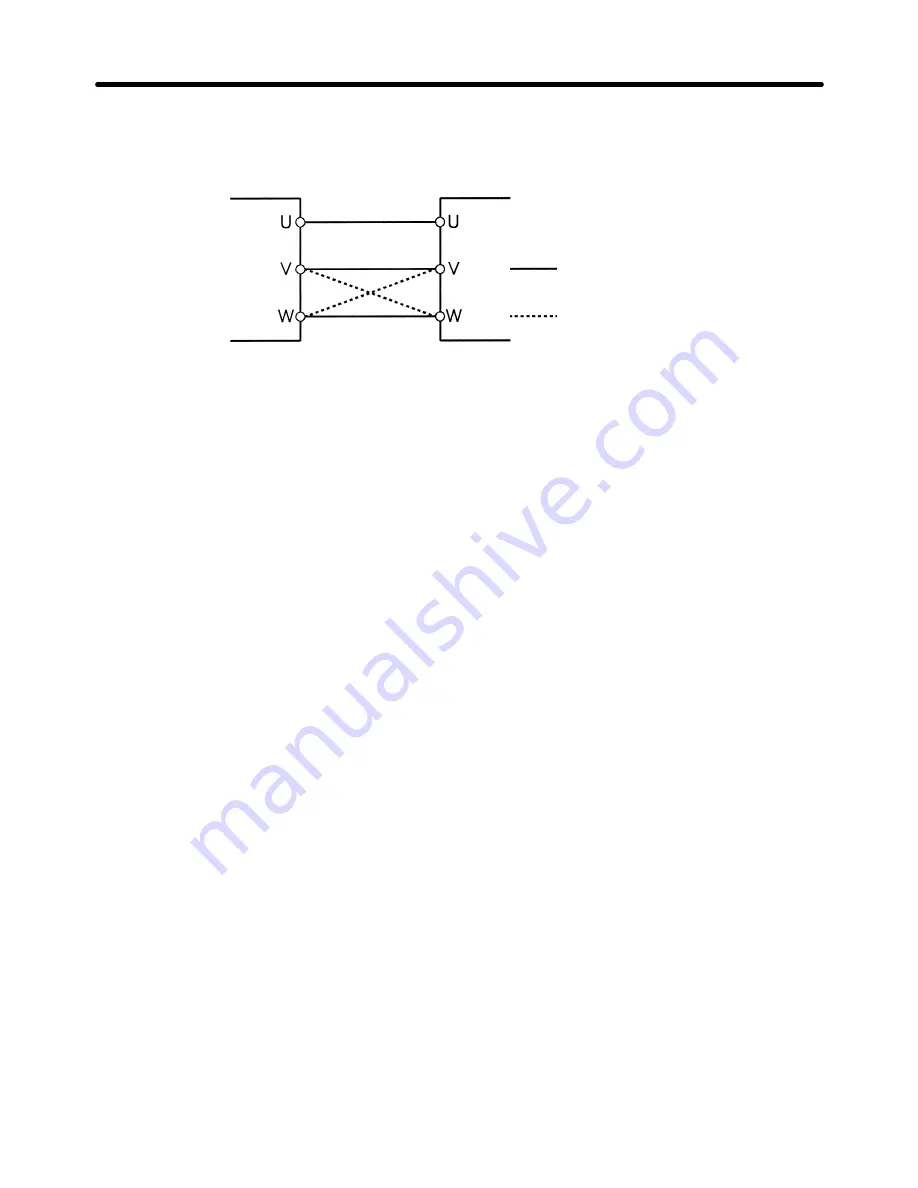
To reverse the direction of rotation, switch the wires of two phases of U, V, and W as
shown below.
Inverter
Motor
Forward rotation
Reverse rotation
5-2-4 Motor Deceleration is Too Slow
H
Deceleration Time is Too Long Even if a Braking Resistor is
Connected.
•
Value 0 (stall prevention during deceleration) is set in n33.
When a braking resistor is connected, always set “1” (no stall prevention during decel-
eration) in n33. If “0” is set, the braking resistor will not be used.
•
The deceleration time set in n21 is too long.
Check the deceleration time setting.
•
Motor torque is insufficient.
If the constant settings are normal and overvoltage does not occur, motor capacity is
insufficient.
Motor capacity should be increased.
5-2-5 Vertical-axis Load Drops when Brakes are
Applied
•
Sequence is incorrect.
The Inverter remains in DC braking status (50% of the n31 setting) for 0.5 second after
deceleration is complete. Modify the sequence so that brakes are applied when the
Inverter enters DC braking status.
•
Brakes are inappropriate.
Always use control brakes, not holding brakes.
Operation
Chapter 5
Summary of Contents for SYSDRIVE 3G3EV SERIES
Page 1: ...USER S MANUAL SYSDRIVE 3G3EV Standard Models Compact Low noise Inverter Cat No I011 E1 3...
Page 5: ...Chapter 1 Getting Started 1 1 Items to be Checked when Unpacking 1 2 Precautions 1...
Page 9: ...Chapter 2 Overview 2 1 Features 2 2 Component Names 2...
Page 14: ...Chapter 3 Design 3 1 Installation 3 2 Wiring 3...
Page 72: ...Chapter 6 Specifications 6 1 Specifications of Main Unit 6...


