The drive calculates the motor primary voltage loss using the output current and the terminal resistance value (E2-05) and
then adjusts the output voltage to compensate insufficient torque at start or when load is applied. The effect of this voltage
compensation can be increased or decreased using parameter C4-01.
Adjustment
Although this parameter rarely needs to be adjusted, small changes in increments of 0.05 may help in the following
situations:
• Increase this setting when using a long motor cable.
• Decrease this setting when motor oscillation occurs.
Adjust C4-01 so that the output current does not exceed the drive rated current.
u
C6: Carrier Frequency
n
C6-01: Drive Duty Mode Selection
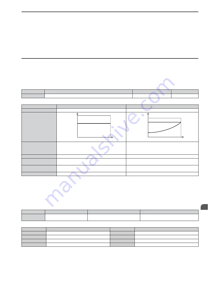
The drive has two different duty modes from which to select based on the load characteristics. The drive rated current,
overload capacity , and carrier frequency will change depending upon the duty mode selection. Use parameter C6-01 (Duty
Cycle) to select Heavy Duty (HD) or Normal Duty (ND) for the application. The default setting is ND.
Refer to
Specifications on page 161
for details about the rated current.
No.
Parameter Name
Setting Range
Default
C6-01
Duty Mode Selection
0 or 1
0
Table 5.6 Differences between Heavy and Normal Duty
Mode
Heavy Duty Rating (HD)
Normal Duty Rating (ND)
C6-01
0
1
Characteristics
100 %
100 %
0
Motor Speed
Rated Load
Overload
150 %
Motor Speed
0
100 %
100 %
120 %
Rated Load
Overload
Application
Use Heavy Duty Rating for applications requiring a high
overload tolerance with constant load torque. Such
applications include extruders and conveyors.
Use Normal Duty Rating for applications in which the torque
requirements drop along with the speed. Examples include
fans or pumps where a high overload tolerance is not
required.
Over load capability (oL2)
150% of drive rated Heavy Duty current for 60 s
120% of drive rated Normal Duty current for 60 s
L3-02 Stall Prevention
during Acceleration
150%
120%
L3-06 Stall Prevention
during Run
150%
120%
Default Carrier Frequency
8/10 kHz
2 kHz Swing PWM
Note:
By changing the Duty Mode the drive maximum applicable motor power changes and the E2-
parameters are automatically set to
appropriate values.
n
C6-02: Carrier Frequency Selection
Parameter C6-02 sets the switching frequency of the drive’s output transistors. It can be changed in order to reduce audible
noise and also reduce leakage current.
Note:
The drive rated current is reduced when the carrier frequency is set higher than the default value.
Refer to Rated Current Depending on
Carrier Frequency on page 80
.
No.
Parameter Name
Setting Range
Default
C6-02
Carrier Frequency Selection
1 to 7, F
Determined by o2-04.
Reset when C6-01 is changed.
Settings:
C6-02
Carrier Frequency
C6-02
Carrier Frequency
1
2.0 kHz
5
12.5 kHz
2
5.0 kHz
6
15.0 kHz
3
8.0 kHz
7
Swing PWM
4
10.0 kHz
F
User defined (C6-03 to C6-05)
Note:
Swing PWM uses 2.0 kHz carrier frequency as a base but by applying special PWM patterns the audible noise of the motor is kept low.
Guidelines for Carrier Frequency Parameter Setup
5.3 C: Tuning
SIEP C710606 33A OYMC AC Drive – J1000 User Manual
79
5
Parameter Details


