OMRON ELECTRONICS LTD
●
Technical Support: 0870 752 0871 or visit www.myOMRON.com
32
Pressing the top-right ‘next’ arrow takes you to the screen shown below. From here you
will be able to select control and monitoring of the inverter or servo drive.
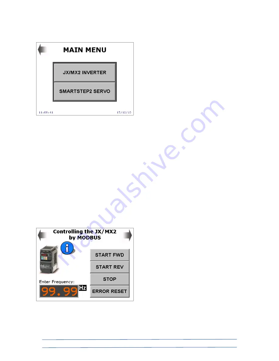
If you selected the “JX/MX2 INVERTER” option, you will see the screen below. A single
“Inverter Refresh” function block within the PLC program controls up to 31 drives, which
can be a mixture of JX and MX2 models.
Touching the “Enter Frequency” display box brings up a numeric keypad, allowing you to
enter a speed reference for the inverter. Note that this value is entered without a decimal
point, e.g. if you enter “1234”, a value of 12.34Hz will be the speed reference. By default,
the JX/MX2 has a maximum frequency reference value of 50.00Hz. Although a maximum
value of 400.00Hz is possible (via settings in the drive), the HMI limits the input value to
50.00Hz.
“START FWD” and “START REV” will cause the motor to accelerate to the input frequency
in a clockwise or counter-clockwise direction. The acceleration and deceleration rates are
set to the inverter defaults, being 10s. Note that this figure is to reach the maximum
frequency (50.00Hz), so if, for example, you set a frequency of 25.00Hz, it would take the
motor 5s to reach this figure from standstill. If the drive goes into error for any reason (this
would generally only happen if a motor was connected, due to mechanical overload
problems), the inverter can be reset from the HMI by pressing the “ERROR RESET” button,
once the cause of the fault has been identified and rectified.
Pressing the top-right “next” arrow takes you on to the inverter monitoring screen…
The advantage of controlling drives by communications over a network is that all the status
information for each unit can be monitored.


