OMRON ELECTRONICS LTD
●
Technical Support: 0870 752 0871 or visit www.myOMRON.com
13
Using the built-in safety features of the MX2 inverter
The MX2 inverter enables safety compliance to
PLd
(“Performance Level d”),
ISO13849-2
cat4, SIL3
, when used with a suitable safety relay unit such as the Omron G9SA-301.
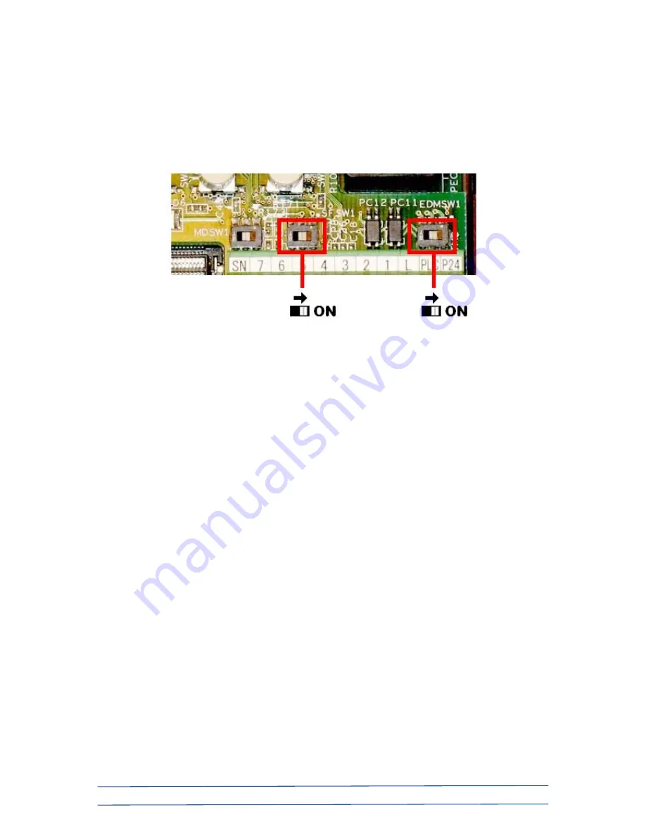
Ensure that power is removed from the MX2 and remove the front cover. Just above the
screw terminal block are three single DIP switches in a horizontal row…
Turning the middle switch to the ON position sets digital inputs 3 and 4 to be used as
normally-closed safety inputs. This action automatically forces drive parameters C003=77
and C004=78 to define the use of these safety inputs.
Turning the right-most DIP switch to the ON position defines that output terminal 11 is to
be used as an external safety monitor (EDM) output.
The wiring diagram on the following page assumes that a single 2 x NC (normally closed)
contact emergency stop switch is to be used with a single MX2 inverter.
The Omron G9SA-301 safety relay unit is shown wired for manual reset (i.e., the MX2 will
not be reset until the button is pressed), but it can, of course, be wired to automatically
reset once the E-stop button is released. Please refer to G9SA manual ref J121-E2-03A
for alternative wiring details.
The MX2’s “P24” (24VDC) terminal provides power to the safety relay’s I/O circuit (G9SA
terminals 13 and 23).
Please ensure that the metal jumper across the “L” and “PLC” terminals of the MX2
remains in place (this is its factory default position). This is the MX2’s internal power
supply 0VDC connection for I/O connections.


