CompoNet
TM
Digital Sensor Communications Unit
E3NW-CRT
Cat. No. E430-E1-04
User's Manual
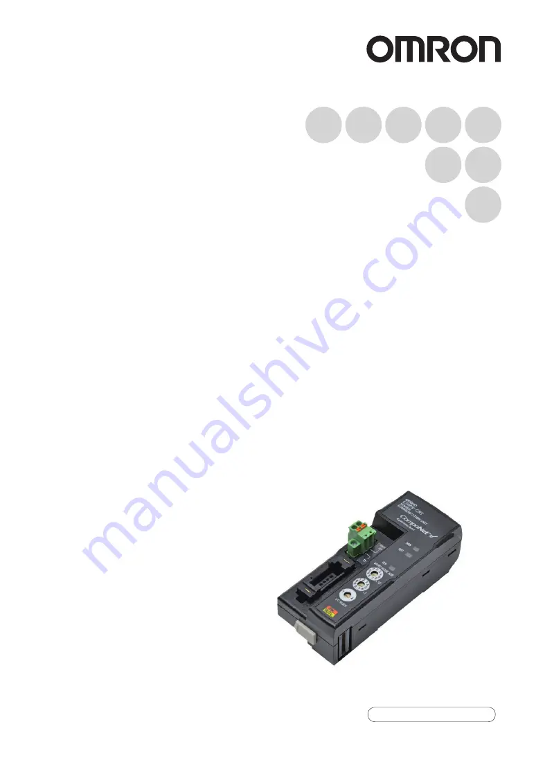
Page 1: ...CompoNet TM Digital Sensor Communications Unit E3NW CRT Cat No E430 E1 04 User s Manual ...
Page 2: ... trademarks of ODVA Other product names and company names used in this manual are the trademarks or registered trademarks of the respective companies The copyright to the Digital Sensor Communications Unit belongs to OMRON Corporation Introduction Intended Audience This manual is intended for the following personnel who must also have knowledge of electrical systems an electrical engineer or the e...
Page 3: ...ction 5 Introduction Section 1 Section 2 Section 3 Section 4 Section 5 Application Considerations Please read first Overview Installation and Connections CompoNet Communications Specifications Using the Distributed Sensor Unit User s Manual Sensor Communications Unit E3NW CRT CompoNet Appendices ...
Page 4: ...replace in the form originally shipped with Buyer responsible for labor charges for removal or replace ment thereof the non complying Product ii repair the non complying Product or iii repay or credit Buyer an amount equal to the purchase price of the non complying Product provided that in no event shall Omron be responsible for warranty repair indemnity or any other claims or expenses regarding t...
Page 5: ...de applicable third party certifi cation documents identifying ratings and limitations of use which apply to the Product This information by itself is not sufficient for a complete determination of the suitability of the Product in combination with the end product machine system or other applica tion or use Buyer shall be solely responsible for determining appropriateness of the particular Product...
Page 6: ...y be changed at any time based on improve ments and other reasons It is our practice to change part numbers when published rat ings or features are changed or when significant construction changes are made However some specifications of the Product may be changed without any notice When in doubt special part numbers may be assigned to fix or establish key specifica tions for your application Pleas...
Page 7: ...ng disassembly The triangle symbol indicates precautions including warnings The specific operation is shown in the triangle and explained in text This example indicates a general precaution The filled circle symbol indicates operations that you must do The specific operation is shown in the circle and explained in text This example shows a general precaution for something that you must do WARNING ...
Page 8: ...tions Unit may remain ON or OFF due to deposition or burning of the output relays or destruction of the output transis tors As a countermeasure for such problems external safety measures must be provided to ensure safety in the system 4 When the 24 VDC output service power supply to the PLC is overloaded or shortcircuited the voltage may drop and result in the outputs being turned OFF As a counter...
Page 9: ...its to the DIN Track Be sure that all the terminal screws and cable connector screws of the product are tightened to the torque specified in the relevant manuals Be sure that the screws of the terminal block are tightened to the torque specified in the relevant manuals Insufficient tightening torque may result in fire malfunction or failure Always use specified communications cables and connectors...
Page 10: ...of the following Changing the operating mode of the PLC Force setting force resetting bits in memory Changing the present value or any set value of any word from the user program Do not use thinner or similar solvent for cleaning Use commercial alcohol Use a dedicated packing box to transport the Unit Avoid excessive shock or vibration during transportation External Circuits Install external break...
Page 11: ... Wrong wiring may cause a failure of the Unit Wire the Unit properly as indicated in this manual Use the correct wiring parts to perform wiring Take appropriate and sufficient countermeasures when using the Unit in the following locations Locations subject to static electricity or other forms of noise Locations subject to strong electromagnetic fields Locations subject to possible exposure to radi...
Page 12: ... specify the Sensor unit number of the Sensor Amplifier Unit for which the command is intended as the Instance ID The specified numbers of bytes for the class ID instance ID and attribute ID depend on the master When a message is sent from an OMRON CompoNet Master Unit specify the class ID and instance ID in two bytes four digits and the attribute ID in one byte two digits Write Data This is not r...
Page 13: ...the seven segment display on the Amplifier Units are enclosed in brackets Visual Aids Indicates points that are important to achieve the full product performance such as operational pre cautions and application procedures Indicates pages where related information can be found Indicates information helpful in operation ...
Page 14: ...12 Introduction E3NW CRT User s Manual Introduction Reading This Manual ...
Page 15: ...Connections 21 Specifications and Dimensions 22 Specifications 22 Dimensions 24 Connecting Sensor Amplifier Units 26 Connectable Sensor Amplifier Units 26 Number of Connectable Sensor Amplifier Units 27 Sensor Amplifier Unit Connection and Identification Unit Numbers 29 Installation 30 Installation Procedure 30 Removal Procedure 31 CompoNet Communications Specifications 33 Overview of the Sensor C...
Page 16: ...it 64 Mounting and Removing Distributed Sensor Units 65 Installation Procedure 65 Removal Procedure 66 Installing a DS Bus Network 67 Precautions for Installing a DS Bus Network 67 Preparing to Install the Network 68 Connecting the Communications Cables and Connectors 69 Distributed Sensor Unit Power Supply Specifications and Connections 71 Precautions on Supplying Unit Power 71 Unit Power Supply ...
Page 17: ...anual Introduction Introduction Contents Appendices 79 Command Descriptions and Data Formats 80 Command Response Time Reference Values 94 Troubleshooting 95 CompoNet Device Profile 97 Device Profile 97 Revision History 98 ...
Page 18: ...16 E3NW CRT User s Manual Introduction Contents Introduction MEMO ...
Page 19: ...17 E3NW CRT User s Manual Section 1 Overview S e c t i o n 1 Overview Features and System Configuration 18 Overview 18 Features 19 System Configuration 20 ...
Page 20: ...ications Unit is a communications slave that is used to monitor Sensor Amplifier Unit ON OFF outputs and detection levels write parameters and perform operations between Digital Sensors and a PLC with CompoNet communications ON OFF outputs can be monitored with remote I O communications Also parameters can be read and written with explicit messages ...
Page 21: ... host master PLCs with remote I O communications without any programming Message Communications You can send commands explicit messages from the PLC to read and write parameters such as detection levels and thresholds and perform operations such as tuning Dummy Sensor Registration You can register Dummy Sensors so that you do not need to change the I O assignments even if the number of Sensor Ampl...
Page 22: ...ection 1 Features and System Configuration System Configuration E3NW CRT Sensor Communications Unit with CompoNet Communications Sensor Amplifier Units CompoNet Configurator CompoNet master PLC Serial connection CompoNet Sensor Head CompoNet slave ...
Page 23: ...s Specifications and Dimensions 22 Specifications 22 Dimensions 24 Connecting Sensor Amplifier Units 26 Connectable Sensor Amplifier Units 26 Number of Connectable Sensor Amplifier Units 27 Sensor Amplifier Unit Connection and Identification Unit Numbers 29 Installation 30 Installation 30 Removal Procedure 31 ...
Page 24: ... power supplied to Sensors at 24 VDC 70 mA max Does not include the current supplied to Sensors Indicators MS machine status indicator green red NS network status indicator green red SS Sensor status indicator green red Vibration resistance destruction 10 to 60 Hz with a 0 7 mm double amplitude 50 m s2 at 60 to 150 Hz for 1 5 hours each in X Y and Z directions Shock resistance destruction 150 m s2...
Page 25: ...Flat Cable I and Flat Cable II are all different types of cable To use more than one type of cable at a time Repeater Units must be used to separate them on trunk lines and sub trunk lines Communications distance and wiring Refer to Cable Types Baud Rates and Maximum Distances in the CompoNet Master Units Operation Manual Cat No W456 Signal lines Two lines BDH communications data high and BDL comm...
Page 26: ...ations Connector provided FK MCP 1 5 2 STF 3 5 AU 4 2 43 28 6 38 8 19 5 13 1 36 7 32 5 DIN Track sold separately PFP N 76 6 46 6 60 9 102 5 105 1 93 8 32 2 49 8 35 36 7 52 7 10 10 E3NW CRT 0 6 0 2 13 1 49 69 86 9 34 3 25 4 42 9 52 8 36 7 35 44 5 Cap and connector DIN Track sold separately PFP N Connector provided FK MCP 1 5 2 STF 3 5 AU 20 95 7 30 4 E3NW DS ...
Page 27: ...or ST indicator Incident level white digital Threshold level green digital OUT2 indicator OUT2 selection indicator OUT1 selection indicator OUT1 indicator 114 max value with cover open 10 11 5 13 8 159 7 max value with cover open 152 max value with cover open 37 33 5 39 5 49 5 32 1 26 29 9 Optical communications L D indicators Mounted to DIN Track PFP N DIN Track sold separately E3NC SA0 2 6 152 m...
Page 28: ...it can be connected to the following Sensor Amplifier Units Type Model number Features Smart Fiber Amplifier Unit E3NX FA0 A standard easy to operate and easy to configure Fiber Amplifier Unit Smart Laser Amplifier Unit E3NC LA0 A Laser Sensor that can reliably detect workpieces even with a small spot diameter Smart Laser Amplifier Unit CMOS E3NC SA0 A CMOS type Laser Sensor that can reliably dete...
Page 29: ...able Sensors Features Unit with CompoNet Communications E3NW CRT I O Mode 1 15 max Two input words outputs for 15 Sensors with two outputs each for a total of 30 outputs and two status bits are allocated as I O Explicit messages are used to change settings and perform tuning This Sensor Amplifier Unit is best for connections to an OMRON NJ series CJ series or CS series master I O Mode 2 16 max Thi...
Page 30: ... Distributed Sensor Units Sensor Communications Unit DS Bus communications cable First Sensor Distribution Unit Termination setting switch OFF Second Sensor Distribution Unit Termination setting switch OFF nth Sensor Distribution Unit n is a maximum of 8 Termination setting switch ON L2 L1 Ln Unit 1 Unit 2 Unit 3 Unit 4 Unit 5 Unit 6 Unit 7 Unit 8 Unit 9 ...
Page 31: ...ommunications Unit The Sensor Communications Unit identifies the connected Sensor Amplifier Units according to their unit numbers Unit numbers of Sensor Amplifier Units are assigned to the units from unit number 1 starting from the Sensor Communications Unit Each Sensor Amplifier Unit has two outputs Sensor Output 1 and Sensor Output 2 Unit 1 Unit numbers are in ascending order from the left DIN T...
Page 32: ...he Unit onto the DIN Track 2 Press the bottom part of the Unit onto the DIN Track 3 Remove the protective cap from the right side of the Sensor Communications Unit Then slide the Sensor Amplifier Unit align the hooks on the connector with the Sensor Communications Unit and press the Units together until you hear them lock into place DIN Track Sensor Communications Unit Press Sensor Amplifier Unit ...
Page 33: ... far right end Do not reverse the order of steps 1 and 2 above Doing so may reduce the mounting strength on the DIN Track After you have completed the above procedure check to make sure that the E3NW CRT is mounted securely into place Removal Procedure Use the following procedure to remove the Unit 1 Slide the Sensor Amplifier Units to separate them from the Sensor Communications Unit DIN Track En...
Page 34: ...32 Section 2 Installation and Connections E3NW CRT User s Manual Section 2 Installation 2 Press in on the Sensor Communications Unit toward the DIN Track and lift up to remove it ...
Page 35: ... Remote I O Communications Application Example 37 Explicit Message Communications Application Example38 Part Names 39 Part Names and Functions 39 Operating Procedure 41 Operating Procedure 41 CompoNet Remote I O Communications 42 Assigning Data in the Master 42 Explicit Message Communications 49 Basic Format of Explicit Messages 49 Read and Write Commands 51 Operation Execution Commands 56 Error C...
Page 36: ...et ON OFF outputs can be monitored with remote I O communications You can also read and write parameter with explicit messages You can register Dummy Sensors so that you do not need to change the I O assignments even if the number of Sensor Amplifier Units changes Explicit messages are also used to register Dummy Sensors When using this Digital Sensor Communications Unit also refer to the followin...
Page 37: ...ompoNet master or other device that supports explicit communications I O Mode 2 6 words in input area 6 words in output area The following data is sent to the master ON OFF output data for a maximum of 16 Sensors I O command area data to control changing settings with I O I O Command Execution In progress Flag Explicit Communications In progress Flag Sensor Error Status 16 max Use this mode when c...
Page 38: ...e commands to the E3NW CRT Sensor Communications Unit Type Communications Sending an Explicit Read Write command Reads or writes parameters such as the detection levels or threshold values Sending an explicit operation command Performs an operation such as tuning Unit 1 Unit 2 Unit 15 CompoNet Unit CPU Unit PLC Ladder program Example CMND instruction Explicit message CompoNet Sensor Heads Sensor A...
Page 39: ...Input Area Fixed Allocation Area 1 Refer to CompoNet Remote I O Communications on page 42 in Section 3 CompoNet Communications Specifications for actual settings Bits 15 14 13 12 11 10 09 08 07 06 05 04 03 02 01 00 Word m Word m 1 m Word address for node address 00 in the input area Sensor Amplifier Unit ON OFF output status for Unit 1 CompoNet Unit CS1W CRM21 Fixed remote I O communications alloc...
Page 40: ...64 hex 100 S D01000 2 8 0 2 Command code D01001 1 0 0 0 Slave node address 00 D01002 0 0 1 0 Service code 10 hex D01003 0 0 9 C Class ID 9C hex D01004 0 0 0 1 Instance ID 01 hex unit number D01005 7 2 6 4 Attribute ID 72 hex Data 64 hex 4th byte least significant D01006 0 0 0 0 Data 00 3rd byte Data 00 2nd byte D01007 0 0 0 0 D D02000 Set the first word address to store the response data C D00000 ...
Page 41: ...s and Functions Rotary switches Indicators Communications connector This connector is for CompoNet communications When connecting to an E3NW CRT power is supplied from the communications connector No power cable is required DS Bus communications connector This connector connects to an E3NW DS Distributed Sensor Unit ...
Page 42: ...unications status Green Lit Communications with Sensor Amplifier Unit are normal Red Lit Number of Sensor Amplifier Units is inconsistent OFF Waiting for communications with the Sensor Amplifier Units and power OFF MS Lit green when the Unit is normal NS Lit green when network is normal online and connected SS Lit green when communicating with a Sensor Amplifier Unit CompoNet node address setting ...
Page 43: ...on page 30 in Section 2 Installation and Connections 3 Connecting the CompoNet Communications Connector Connect the CompoNet communications connector The CompoNet communications power supply V V provides DC power to the Sensor Communications Unit and all connected Sensor Amplifier Units 4 Setting the Rotary Switches Two upper switches Set the CompoNet node address 0 to 62 One lower switch Set the ...
Page 44: ...on levels and make settings 15 max 2 Mode for using the I O command area to monitor detection levels and make settings 16 max Bit Description Bit Description 00 Unit 1 ON OFF output data 1 00 Unit 9 ON OFF output data 1 01 Unit 1 ON OFF output data 2 01 Unit 9 ON OFF output data 2 02 Unit 2 ON OFF output data 1 02 Unit 10 ON OFF output data 1 03 Unit 2 ON OFF output data 2 03 Unit 10 ON OFF output...
Page 45: ...put Word m 1 Bit Description Bit Description 00 Unit 1 ON OFF output data 1 00 Unit 9 ON OFF output data 1 01 Unit 1 ON OFF output data 2 01 Unit 9 ON OFF output data 2 02 Unit 2 ON OFF output data 1 02 Unit 10 ON OFF output data 1 03 Unit 2 ON OFF output data 2 03 Unit 10 ON OFF output data 2 04 Unit 3 ON OFF output data 1 04 Unit 11 ON OFF output data 1 05 Unit 3 ON OFF output data 2 05 Unit 11 ...
Page 46: ...his flag turns ON when explicit message communications are in progress with a Sensor Amplifier Unit Do not send a new explicit message or use I O to send a command to the Unit while this flag is ON 3 BUSY_IO Command Execution in Progress with Sensor Amplifier Unit Using I O This output turns ON when remote I O communications are in progress with a Sensor Amplifier Unit Do not send a new explicit m...
Page 47: ...er Command Code and Write Data are read and the command is executed 8 Sensor Output Number Specify the sensor output number Both 00 hex IN1 01 hex IN2 02 hex Specify 00 hex for commands to the Sensor Communications Unit 9 Multi command Destination Bit Specification Specify the command destination Turn ON the bits between 00 and 15 that correspond to the unit numbers of the Sensor Amplifier Units Y...
Page 48: ... Outputs 1 and 2 0x42 0xA2 OK OK OK Operating Mode Outputs 1 and 2 0x44 0xA4 OK OK OK Detection Both 0x45 0xA5 OK OK OK Timer Setting Outputs 1 and 2 0x47 0xA7 OK OK OK Timer Time 1 Outputs 1 and 2 0x48 0xA8 OK OK OK Timer Time 2 Outputs 1 and 2 0x49 0xA9 OK OK OK DPC Setting Both 0x4A 0xAA OK OK NA Display Switch Both 0x50 0xB0 OK OK OK Reversed Display Both 0x51 0xB1 OK OK OK Channel Display Bot...
Page 49: ... Level Both 0x72 0xD2 OK OK NA Execute Power Tuning Both 0xD3 OK OK NA One point Tuning Outputs 1 and 2 0xD4 NA NA OK Flashing Both 0xD7 OK OK OK Clear Flashing Both 0xDE OK OK OK Initialize Both 0xD8 OK OK OK Self Trigger Level Both 0x79 0xD9 NA NA OK Tuning without a Workpiece Outputs 1 and 2 0xDA NA NA OK Background Suppression Both 0x7B 0xDB NA NA OK Error Flag Description 01 A command that ca...
Page 50: ... turn OFF the TRIGGER signal E When the TRIGGER signal is turned OFF the BUSY and NORM_RES signals also turn OFF F After the BUSY and NORM_RES turn OFF the next command execute signal is turned ON G BUSY and NORM_RES will remain ON until the host turns OFF the TRIGGER signal Read Write or Execute Command Processing Is Failed A Turn ON the TRIGGER signal from the host Set the Unit Number Sensor Cha...
Page 51: ... command code processing target and processing details With this Sensor Communications Unit specify the Sensor unit number of the Sensor Amplifier Unit for which the command is intended as the Instance ID The specified numbers of bytes for the class ID instance ID and attribute ID depend on the master When a message is sent from an OMRON CompoNet Master Unit specify the class ID and instance ID in...
Page 52: ...read data is stored only when a read command has been sent Error Code The error code for the explicit message Refer to Error Codes on page 59 With this Sensor Communications Unit some commands such as power tuning commands require time to be processed Change the timer set value for these commands Set the CompoNet message monitoring timer to 30 seconds or longer Refer to 6 1 5 Message Monitoring Ti...
Page 53: ...pply to read commands 4 The write data must be in little endian format 4 Output 1 specification Bit 0 ON 01 hex Output 2 specification Bit 1 ON 02 hex Both outputs specified to Communications Unit All OFF 00 hex 5 Multi Sensor No consists of two bytes of data where bit 0 corresponds to Unit 1 and the bit 15 corresponds to Unit 16 and must be input in little endian format as shown in the example be...
Page 54: ...ommunications Response Format Normal Error Number of received bytes Destination network address Service code Read Data read commands only 008E Read 0090 Write 2 bytes 2 bytes 2 bytes 4 bytes Number of received bytes Destination network address Service code Error code 0094 2 bytes 2 bytes 2 bytes 4 bytes ...
Page 55: ... Response Setting Sets the response to return when an explicit message is sent to a Dummy Sensor 0x9C 0x00 0x70 Number of Mounted Sensors Reads the number of connected Sensor Amplifier Units including Dummy Sensors 0x9F 0x00 0xC0 Sensor Warning Status Reads the warning status of the Sensor Amplifier Unit 0x9F 0x00 0xC1 Sensor Model Reads the model of the Sensor Amplifier Unit 0x9F Unit No 0xC9 OK ...
Page 56: ...0x9C Unit No 0x50 OK OK OK Hysteresis Width Setting Reads or writes the Hysteresis Width Setting 0x9C Unit No 0xD5 OK OK OK Hysteresis Width 1 Reads or writes Hysteresis Width 1 settings 0x9C Unit No 0xD6 OK OK OK Hysteresis Width 2 Reads or writes Hysteresis Width 2 settings 0x9C Unit No 0xD7 OK OK OK Keep Setting Reads or writes the Keep Settings 0x9C Unit No 0xD8 NA NA OK Hold Mode Setting Read...
Page 57: ...ts in Section 5 Appendices for details on read and write command data Self Trigger Level Reads or writes the Self Trigger Level settings 0x9C Unit No 0xE1 NA NA OK Background Suppression Reads or writes the Background Suppression settings 0x9C Unit No 0xE4 NA NA OK Explicit message Function Command Applicable Sensor Amplifier Units Class ID Instance ID Attribute ID FA0 LA0 SA0 OK Supported NA Not ...
Page 58: ...ce ID to 00FF hex and append the following bytes after the attribute ID 4 Output 1 specification Bit 0 ON 01 hex Output 2 specification Bit 1 ON 02 hex Both outputs specified to Communications Unit All OFF 00 hex 5 Multi Sensor No consists of two bytes of data where bit 0 corresponds to Unit 1 and the bit 15 corresponds to Unit 16 and must be input in little endian format as shown in the example b...
Page 59: ... 3 Explicit Message Communications Response Format Normal Error Number of received bytes Destination network address Service code 0096 fixed 2 bytes 2 bytes 2 bytes Number of received bytes Destination network address Service code Error code 0094 fixed 2 bytes 2 bytes 2 bytes 2 bytes ...
Page 60: ...t No 0xD3 OK OK OK Clear Channel Display Cancels the channel display on the Sensor Amplifier Unit 0x9E Unit No 0xD4 OK OK OK Flash Display Setting Flashes the Sensor Amplifier Unit s display 0x9E Unit No 0x52 OK OK OK Cancel Flash Display Setting Stops flashing the Sensor Amplifier Unit s display 0x9E Unit No 0x53 OK OK OK Maximum Sensitivity Tuning Performs maximum sensitivity tuning 0x9E Unit No...
Page 61: ...n data is out of range The number of connected Sensors is not within between 1 and 16 The number of Units specified for detection level monitoring is not between 1 and 16 0x16FF Object does not exist The specified instance ID is not supported The unit number specified in the instance ID exceeds the number of connected Sensors 0x15FF Too much data The data is longer than the specified size 0x13FF N...
Page 62: ...340 for detailed information on instructions CMND S D C S D01000 0 2802 hex Command code 1 1000 hex Sensor Communications Unit address 1000 I O Mode 1 address 00 2 0010 hex Service code 10 hex 3 009C hex Class ID 9C hex 4 0001 hex Instance ID 01 hex 5 7264 hex Attribute ID 72 hex Write data 4th byte least significant 64 hex 6 0000 hex Write data 3rd byte 00 hex Write data 2nd byte 00 hex 7 0000 he...
Page 63: ...munications Specifications Section 3 Explicit Message Communications 5 00C8 hex Response monitoring time 30 seconds Response D02000 0 2802 hex 1 0000 hex 2 0004 hex 3 1000 hex 4 0090 hex Response source node address 0 00 hex Normal completion 90 hex ...
Page 64: ...cations Port Error Flag Set 000F in D00000 number of bytes to send 15 Set 0008 in D00001 number of bytes to receive 8 Set 0000 in D00002 destination network address 00 Set 0020 in D00003 destination node address 00 destination unit address 20 Set 0000 in D00004 response required communications port 0 retries 0 Set 00C8 in D00005 response monitoring time 30 seconds Set 0001 in CIO 0000 The 15 bytes...
Page 65: ...g a DS Bus Network 67 Preparing to Install the Network 68 Connecting the Communications Cables and Connectors 69 Distributed Sensor Unit Power Supply Specifications and Connections 71 Precautions on Supplying Unit Power 71 Unit Power Supply Specifications 71 Connecting the Unit Power Supply 72 General Specifications of the Distributed Sensor Unit 73 Hardware Specifications of the Distributed Senso...
Page 66: ...odels and features of the Sensor Amplifier Units that can be connected to an E3NW DS Distributed Sensor Unit Type Model number Features Smart Fiber Amplifier Unit E3NX FA0 A standard easy to operate and easy to configure Fiber Amplifier Unit Smart Laser Amplifier Unit E3NC LA0 A Laser Sensor that can reliably detect workpieces even with a small spot diameter Smart Laser Amplifier Unit CMOS E3NC SA...
Page 67: ...on page 24 in Section 2 Installation and Connections for dimensions of each Distributed Sensor Units Installation Procedure Use the following procedure to install the Units 1 Place the top part of the Unit onto the DIN Track 2 Press the bottom part of the Unit onto the DIN Track 3 Remove the protective cap from the right side of the Distributed Sensor Unit Then slide the Sensor Amplifier Unit alig...
Page 68: ...reverse the order of steps 1 and 2 above Doing so may reduce the mounting strength on the DIN Track After you have completed the above procedure check to make sure that the E3NW DS is mounted securely into place Removal Procedure Use the following procedure to remove the Unit 1 Slide the Sensor Amplifier Units to separate them from the Distributed Sensor Unit 2 Press in on the Distributed Sensor U...
Page 69: ...ditions for the communications cables in the network Are there any disconnections Are there any short circuits Are there any problems with connector connections When connecting to the communications connector on each device be sure to insert the wires until they lock into place in the communications cable connector Separate communications cables from high voltage power lines and install them in du...
Page 70: ...Use the recommended product that is given below Sensor Communications Unit DS Bus Communications Connector Enclosed with the E3NW Series Sensor Communications Unit Distributed Sensor Unit DS Bus Communications Connector Enclosed with the E3NW DS Distributed Sensor Unit Ferrite core Two are required Enclosed with the E3NW DS Distributed Sensor Unit Part Manufacturer Model Communications Cable Bando...
Page 71: ...ables and Connectors E3NW series Sensor Communications Unit Connect the communications cable to the DS Bus communications connector on the Communications Unit Clamp a ferrite core enclosed with the Distributed Sensor Unit to the communications cable To Distributed Sensor Unit D terminal D terminal Communications Cable Ferrite core Ferrule ...
Page 72: ...Unit Clamp a ferrite core enclosed with the Distributed Sensor Unit to the communications cable Connect the shield wire on the communications cable between Distributed Sensor Units to the V terminal on only one of the Distributed Sensor Units Do not connect the shield wire to both Units To Communications Unit or Distributed Sensor Unit Communications Cable Communications cable shield wire Ferrite ...
Page 73: ...ing on whether you want to stop the entire system when a power supply problem occurs or if you want to avoid stopping the entire system when possible If you want to avoid stopping the entire system install power supplies in multiple locations and divide the Distributed Sensor Units into groups This will also help to reduce voltage drop and enable you to use smaller cables Unit Power Supply Specifi...
Page 74: ...le wires Recommended Parts We recommend using the following ferrules for the Unit power supply cable We recommend the following screwdriver for the removal of ferrules To 24 VDC Unit power supply Unit power supply cable Ferrule V terminal V terminal Model number Applicable wire size Crimp tool Manufacturer AI0 5 10WH 0 5 mm2 AWG20 CRIMPFOX UD6 product No 1204436 or CRIMPFOX ZA3 Series Phoenix Cont...
Page 75: ...luding the power supplied to Sensors 80 mA max Not including the current supplied to Sensors Noise resistance Conforms to IEC 61000 4 4 1 kV power supply line Vibration resistance 10 to 60 Hz with a 0 7 mm double amplitude 50 m s2 at 60 to 150 Hz for 1 5 hours each in X Y and Z directions Shock resistance 150 m s2 for 3 times each in X Y and Z directions Withstand voltage 500 VAC at 50 60 Hz for 1...
Page 76: ...red Rotary switch setting error WDT error timeout hardware error or RAM check error Flashing No access from the Sensor Communications Unit for 3 seconds or longer Lit Normal operation or sensor not connected error Color Status Description OFF Power is OFF initial confirmations are in progress after turning ON the power or one of the following errors has occurred Hardware error or sensor not connec...
Page 77: ...ltiple Distributed Sensor Units are connected to the Sensor Communications Unit set the addresses of the Distributed Sensor Units in order starting from 1 The setting of the unit address switch is read only once when the power is turned ON Changing this setting after the power is turned ON will have no effect until after the next time the power is turned ON An error will occur and operation will n...
Page 78: ...S Bus termination setting switch for the last Distributed Sensor Unit on the DS Bus network Turn this switch OFF for all other Distributed Sensor Units This is shown in the following figure Termination setting switch Sensor Communications Unit DS Bus communications cable First Sensor Distribution Unit Termination setting switch OFF Second Sensor Distribution Unit Termination setting switch OFF nth...
Page 79: ...S Bus communications cable to this connector Connector type Four pin spring cage connector with lock screws Supported ferrule diameter 0 25 to 0 5 mm2 AWG24 to AWG20 Use ferrules with insulating sleeves Refer to Connecting the Unit Power Supply on page 72 for the recommended ferrules D terminal D terminal V terminal V terminal Name Specification V D 24 VDC Communications data signal D Communicatio...
Page 80: ...78 Section 4 Using the Distributed Sensor Unit E3NW CRT User s Manual Section 4 Hardware Specifications of the Distributed Sensor Unit ...
Page 81: ...RT User s Manual Section 5 Appendices S e c t i o n 5 Appendices Command Descriptions and Data Formats 80 Command Response Time Reference Values 94 Troubleshooting 95 CompoNet Device Profile 97 Device Profile 97 ...
Page 82: ...tup is given in hexadecimal Number of Sensors Available for Communications The number of Sensors that is currently available for communications is given in hexadecimal If Dummy Sensors have been registered this value will be the sum of the actual number of Sensors available for communications plus all registered Dummy Sensors Inconsistent Number of Sensor Amplifier Units This bit turns ON if a com...
Page 83: ...g has occurred This does not apply for I O commands Sensor Power ON This command turns ON the Sensor power supply for all Sensor Amplifier Units connected to the Communications Unit This does not apply to Sensor Amplifier Units that are connected to a Distributed Sensor Unit Sensor Power OFF This command turns OFF the Sensor power supply for all Sensor Amplifier Units connected to the Communicatio...
Page 84: ...Dummy Sensor This setting cannot be changed via I O commands in I O Mode 2 Sensor Model This command reads the model of the Sensor Amplifier Unit that corresponds to the specified unit number Read Detection Level This command reads the detection level incident light level of the Sensor Amplifier Unit that corresponds to the specified unit number and output number The data is given as the two s com...
Page 85: ...that corresponds to the specified unit number To read the Bottom Detection Level you must select the input peak minimum value and interrupted light bottom maximum value P b for the Display Switch Setting The data is given as the two s complement of a 4 byte 8 digit hexadecimal value Threshold Setting 1 This command reads or writes Threshold Value 1 of the Sensor Amplifier Unit that corresponds to ...
Page 86: ...nit number Zero Reset Level This command reads the zero reset level of the Sensor Amplifier Unit that corresponds to the specified unit number The data is given as the two s complement of a 4 byte 8 digit hexadecimal value Bit Description Data 00 to 31 Threshold Setting 2 Data range 1999 FFFFF831 hex to 9999 0000270F hex Bit Sensor status 00 Normal operation For normal operation this bit is always...
Page 87: ...s command sets the timer of the Sensor Amplifier Unit that corresponds to the specified unit number and output number Bit Description Data Output 1 Output 2 00 or 01 Output Mode 0 Normal detection mode 1 Area detection mode 2 Do not use 3 Hold mode SA0 only 0 Normal detection mode 1 Alarm output mode FA0 LA0 2 Error output mode 02 to 31 No applicable data Not used Not used Bit Description Data 00 ...
Page 88: ...r Unit that corresponds to the specified unit number and output number Timer Time 2 is assigned to the OFF delay timer DPC Setting This command sets the DPC of the Sensor Amplifier Unit that corresponds to the specified unit number Bit Description Data 00 to 15 Timer Time 1 Data range 1 00000001 hex to 9999 0000270F hex 16 to 31 No applicable data Always 0 Bit Description Data 00 to 15 Timer Time ...
Page 89: ...s the display on the Sensor Amplifier Unit that corresponds to the specified unit number Channel Display This command sets the channel display of the Sensor Amplifier Unit that corresponds to the specified unit number Clear Channel Display This command clears the channel display of the Sensor Amplifier Unit that corresponds to the specified unit number Bit Description Data 00 Display Switch 0 Thre...
Page 90: ...Amplifier Unit that corresponds to the specified unit number Hysteresis Width Setting This command sets the Hysteresis Width of the Sensor Amplifier Unit that corresponds to the specified unit number Hysteresis Width 1 This command sets Hysteresis Width 1 of the Sensor Amplifier Unit that corresponds to the specified unit number Bit Description Data 00 Eco Mode 0 Eco Mode OFF 1 Eco Mode ON 2 Eco M...
Page 91: ...Output Level of the Sensor Amplifier Unit that corresponds to the specified unit number Maximum Sensitivity Tuning The command executes maximum sensitivity tuning for the Sensor Amplifier Unit that corresponds to the specified unit number and output number This must be executed at least 3 seconds after the full auto tuning setup is performed Bit Description Data 00 to 31 Hysteresis Width 2 Data ra...
Page 92: ...e second point of two point tuning for the Sensor Amplifier Unit that corresponds to the specified unit number and output number Tuning for the first point of two point tuning must be executed first Position Tuning The command executes position tuning for the Sensor Amplifier Unit that corresponds to the specified unit number and output number Tuning for the first point of two point tuning must be...
Page 93: ...Settings This command sets the Power Tuning of the Sensor Amplifier Unit that corresponds to the specified unit number Power Tuning Level This command sets the Power Tuning Level of the Sensor Amplifier Unit that corresponds to the specified unit number Execute Power Tuning This command executes power tuning for the Sensor Amplifier Unit that corresponds to the specified unit number Bit Descriptio...
Page 94: ...ponds to the specified unit number Do not press the button on the Unit to initialize the Sensor during operation When in operation always use this command to perform Sensor initialization Sensor initialization will not reset the Channel Display Display Flash Light OFF and Flashing Settings Self Trigger Level This command sets the Self Trigger Level of the Sensor Amplifier Unit that corresponds to ...
Page 95: ... Formats Background Suppression This command sets Background Suppression of the Sensor Amplifier Unit that corresponds to the specified unit number Bit Description Data 00 Background Suppression 0 Background suppression OFF 1 Background suppression ON 01 to 31 No applicable data Always 0 ...
Page 96: ...message is used The command response time is a reference value only Perform thorough testing in your own environment before use Command response time 1 Test conditions Baud rate 4 Mbps CPU Unit cycle time 1 ms Number of CompoNet Slave Units 1 Communications Configuration Executed Command Item Model number Version CPU Unit NJ301 1100 Version 1 02 CompoNet Master Unit CJ1W CRM21 Version 1 3 CompoNet...
Page 97: ...is faulty Replace the E3NW CRT Unit MS indicator lit green NS indicator lit red CompoNet is in the Busoff state Check the following items and restart the Unit Are the cables the correct length main and auxiliary lines Are any cables short circuited disconnected or loose Is the terminating resistance set only at the ends of the main line Is there too much noise The node address is the same as anoth...
Page 98: ...isconnected Connect the Sensor Amplifier Units correctly The number of connected Sensor Amplifier Units exceeds the maximum allowable number Keep the number of connected Sensor Amplifier Units within the maximum allowable number The total number of connected Sensors including all registered Dummy Sensors must be within the maximum allowable number One of the connected Distributed Sensor Units has ...
Page 99: ... device profile Class ID 0x01 Instance ID 0x01 Attribute ID ID Contents Get Set Value 1 Vendor Y N 47 2 Product type Y N 12 3 Product code Y N 1657 4 Revision Y N 1 1 5 Status bits supported Y N Bit 0 only 6 Serial number Y N Each Unit 7 Product name Y N E3NW CRT 8 State N N Service Code CompoNex service Parameter options 05 Reset None 0E Get_Attribute_Single None ...
Page 100: ...his manual Cat No E430 E1 04 Revision code Reprint code on the back cover only Web Version 3 Revision code Reprint code Date Revised content A 01 July 2013 Original production B 01 September 2013 Page 94 Added information at end of first sentence and added test conditions C 01 July 2014 Page 88 Added setting for Eco Mode LO D 01 April 2015 Removed the logo from the connector diagram Corrected mist...
Page 101: ......
Page 102: ... 60169 U S A Tel 1 847 843 7900 Fax 1 847 843 7787 Regional Headquarters OMRON EUROPE B V Wegalaan 67 69 2132 JD Hoofddorp The Netherlands Tel 31 2356 81 300 Fax 31 2356 81 388 Contact www ia omron com Tokyo JAPAN OMRON ASIA PACIFIC PTE LTD No 438A Alexandra Road 05 05 08 Lobby 2 Alexandra Technopark Singapore 119967 Tel 65 6835 3011 Fax 65 6835 2711 OMRON CHINA CO LTD Room 2211 Bank of China Towe...