background image


Connection manual of XDesignerPlus external devices


8 / 12 

4.3 Communication check 

■ Check the interface settings between external devices - TOP.   
- Resetting the power of TOP, move to the menu screen by clicking on the top of the LCD window. 
-  Check  that  the  settings  of  the  port  [COM  2  or  COM  1]  to  use  in  [Communication  settings]  are  the  same  with  the  settings  of 
external devices. 
■ Check if there is an error in port communication 
- Click on the “Communication check” button in PLC Setup > TOP [ COM 2 or COM 1 ] 
- The diagnostics dialogue box will pop up on the screen, then judge checking status as the contents shown in the box no.3. 

OK! 

Normal communication settings 

Time Out Error! 

Abnormal communication settings 
- It is an error in the settings of a TOP/external device and cable


(reference: communication check sheet)


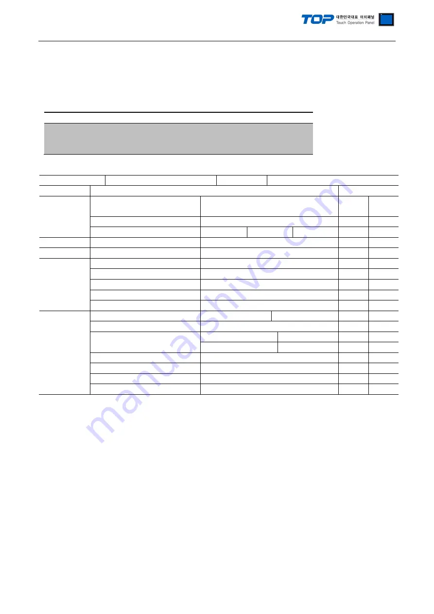
■ Communication check sheet   
- Please check the settings shown in the sheet below if there is an error in the communication connection with external terminals. 

Designer Version 


O.S Version 


Details 

Contents 

check 

System 
configuration 

CPU name 


OK 

NG 


Port name of the other device 


OK 

NG 


Systemconnection method 

1:1 

1:N 

N:1 

OK 

NG 

connectioncable  cable name 


OK 

NG 

PLC Setup 

settings station number 


OK 

NG 


Serial Parity bit 

                                                            [BPS] 

OK 

NG 


Serial data bit 

                                                            [BIT] 

OK 

NG 


Serial Stop bit 

                                                            [BIT] 

OK 

NG 


Serial parity bit 

                                                            [BIT] 

OK 

NG 


Address range 


OK 

NG 

TOP settings 

settings port 

COM 1 

COM 2 

OK 

NG 


driver name 


OK 

NG 


Station number of the other device 

Project Property settings 


OK 

NG 


Communication    check   


OK 

NG 


Serial baud bit 

                                                            [BPS] 

OK 

NG 


Serial data bit 

                                                            [BIT] 

OK 

NG 


Serial Stop bit 

                                                            [BIT] 

OK 

NG 


Serial parity bit 

                                                            [BIT] 

OK 

NG 


Summary of Contents for 3F88L-160

Page 1: ...l devices Page 3 Select a TOP model and external devices 3 Example of system settings Page 4 Explains an example of settings for communication interface between the devices and the relevant external t...

Page 2: ...and OMRON Corporation CAM Positioner Series 3F88L 160 162 is as follows Series CPU Link I F Communicati on method Systemsettings Cable CAM Positioner 3F88L 160 162 Communication Port on CPU Unit RS 23...

Page 3: ...S version specified in the table below according to TOP series Series Version name XTOP HTOP V4 0 Name Select the model name of TOP product External device Vendor Select the vendor of external devices...

Page 4: ...BPS 9600 User settings Serial data bit Bit 7 User settings Serial stop bit Bit 2 User settings Serial parity bit Bit EVEN User settings 1 XDesignerPlus settings After setting the below details in Proj...

Page 5: ...rnal devices as shown below Please refer to the User s Manual of external devices for more detailed settings 1 Set Function No b Parameter No 6 as 1 Set the Parity bit 9600 bps factory setting 2 Switc...

Page 6: ...erface settings Details Contents Signal level Select a serial communication method between TOP External devices COM1 supplies RS 232C only Baud rate Select a serial communication speed between TOP Ext...

Page 7: ...1 mSec Set the TOP s wait time between receiving the response from external devices transmitting the next command request at 0 5000 x 1 mSec TOP COM 2 1 It is the interface settings of TOP for externa...

Page 8: ...It is an error in the settings of a TOP external device and cable reference communication check sheet Communication check sheet Please check the settings shown in the sheet below if there is an error...

Page 9: ...s seen at the connection area of cable connection connector B XTOP COM 2 port 15pin XTOP COM2 Cable connection PLC PIN arrangement Note1 Signal name Pin number Pin number Signal name PIN arrangement N...

Page 10: ...rigin compensation value 4 digit BCD from 0000 to 0359 0719 Address 0002 Leftmost byte Address 0003 Rightmost byte X 0004 0005 Backlash Compensation value Backlash compensation value 4 digit BCD from...

Page 11: ...s for bank1 Address 0070 to 0073 Bank 7 cam data protect setting Address 0074 to 0077 Bank 7 one direction function setting Address 0078 to 007B Bank 7 rotation direction setting X 0080 to 008B Bank8...

Page 12: ...for Bank 8 Same as for Bank 1 X Note1 The 8 digits of data can be read when the P0000 address uses 32BIT Controller Status Read RUN PRGM SET S Address Name Detailed information 32 BIT available Status...

Reviews: