Connection manual of XDesignerPlus external devices
4 / 12
3. Example of system settings
Settings of communication interface in TOP and “CAM Positioner” are recommended as shown below.
3.1 Example of settings 1
The system is set as below.
Details
TOP
“CAM Positioner Series“
Remarks
Serial level (port/channel)
RS-232C (COM2)
RS-232C
User settings
Station number (PLC Address)
─
0
User settings
Serial Parity bit
[BPS]
9600
User settings
Serial data bit
[Bit]
7
User settings
Serial stop bit
[Bit]
2
User settings
Serial parity bit
[Bit]
EVEN
User settings
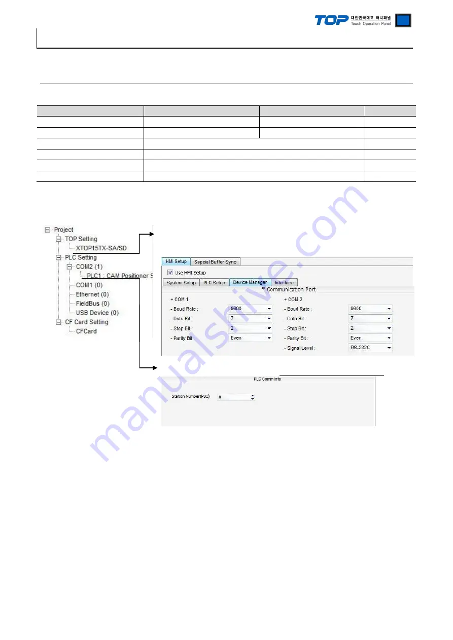
(1) XDesignerPlus settings
After setting the below details in [Project > Project Settings], download the detailed settings using TOP tool.
■ [ Project > Project property > Project > TOP Settings > TOP Name ]
Set a communication interface of TOP tool.
– On the right window, [ HMI Setup > HMI Setup use check > Device manager ]
■ External device settings
Set options of communication driver for “CAM Positioner Series 3F88L-160/162”..
– PLC station number(PLC): The station number same as external devices


