


OMNI 4000/7000 Operations and Maintenance Guide
– Rev F
7-27
Maintenance
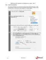
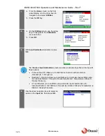
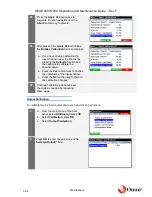
9.
Adjust the
Signal Generator
or configure
the
Transmitter
(whichever is connected)
to output the appropriate
Low
value
according to the selected calibration units.
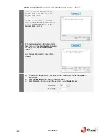
10.
Confirm that the
Live Input (mA/Ohms)
field value is close to the applied value
from the field transmitter or
signal generator.
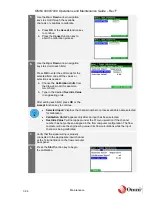
If the value is not close to the applied
value, check:
•
The wiring is connected to the
correct channel.
•
The hardware jumper settings.
See the following sections in the Installation Guide for more information on wiring and
jumper settings:
•
Section 3.7.5 Process I/O Modules for tables on back panel wiring.
•
Appendix A: Jumper Settings for hardware jumper settings.
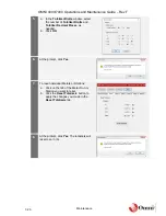
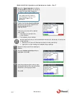
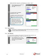
11.
Wait 20 to 30 seconds for the readings to
stabilize.
12.
While the
Applied Input Value?
field is
highlighted, press
OK
.
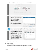
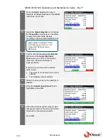
13.
Using the numeric keypad, enter a value
that exactly matches the value at the field
transmitter or the signal generator.
Press
OK
.
Low values are 4.00 mA for a
4
‒20 mA input, 1 V for a 1‒5 V
input, and 25 ohms for an
RTD input.


