background image

27 | 

M 5 7 7 9

6.4.2


    DIO IPSO Definition 

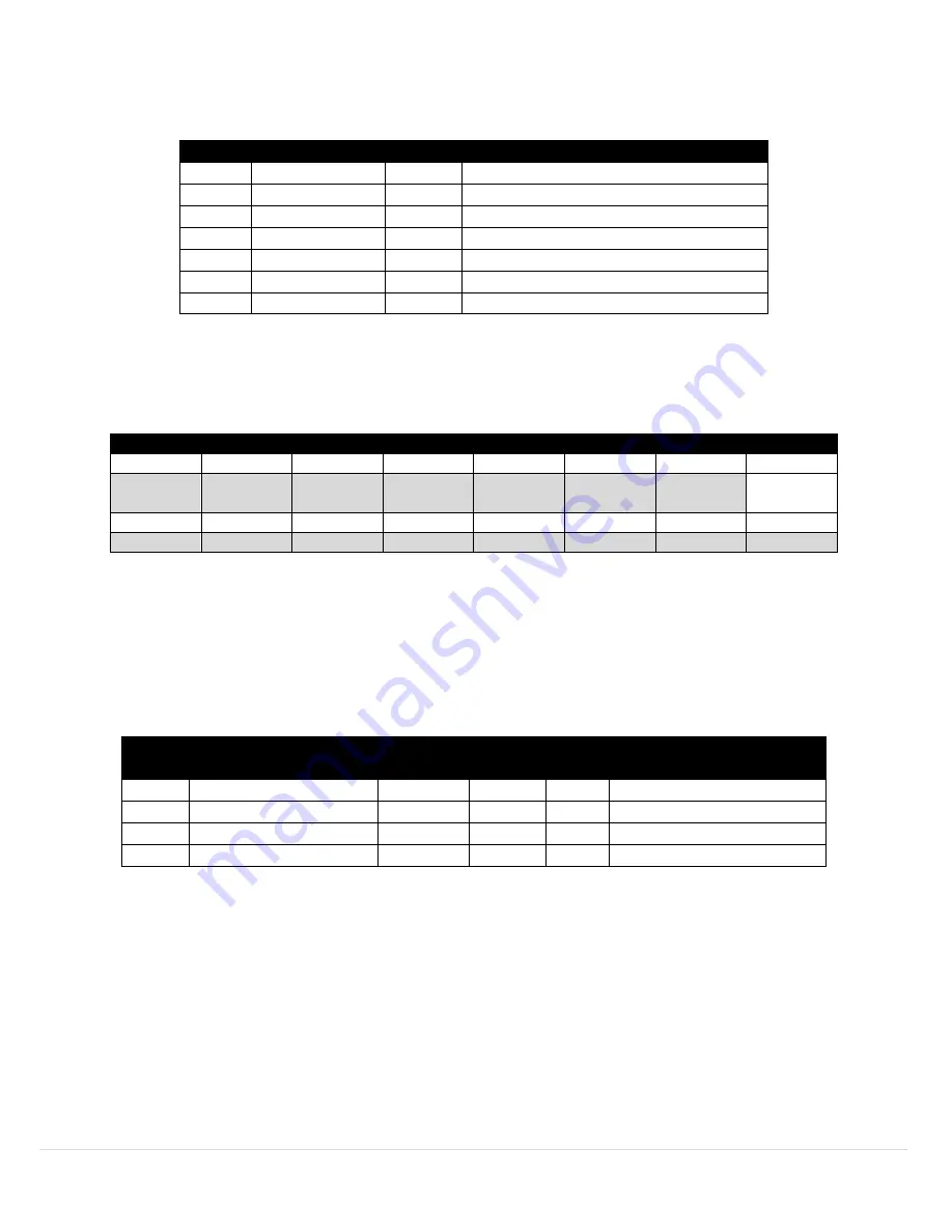
The DIO input IPSO definition provides signal range, measured min/max values, IPSO object type 

information. 

Offset 

Name 

Value 

Description 

0xa8 

Sensor Type 

3349 

Bit Mapped Digital 

0xaa 

Precision 

Provides reading of xxx 

0xac 

Sensor Trigger 

?? 

Write 0x0001 force reset of min / max 

0xb0 

Min Measured 

?? 

Minimum reading since the last reset 

0xb4 

Max Measured 

?? 

Maximum reading since the last reset 

0xb8 

Min Range 

Minimum reading 

0xbc 

Max Range 

Maximum reading 

6.4.2.1


Sensor Trigger Function 

The Sensor Trigger function is used to reset the IPSO min/max values as well as controlling the 

Calibration process.  

Sensor Trigger Function 

Reset 

Min/Max 

15 

14 

13 

12 

11 

10 

Setting the Reset Min/Max bit to 1 will reset the Min/Max values recorded by the IPSO process. No 

User Calibration process is supported on the DIO inputs and all Configuration bits should be written 

as 0. 

6.5


Output Configuration Registers 

Outputs share a common structure which consists of 3-fields mapped to a 16-bit unsigned integer, accessible in the 

Smart Sensor register map. 

Output 

Name 

Modbus 

Address 

I2C 

Address  Size 

Typical Description 

Output 0 Descriptor 

0xf09a 

0x0134  uint16 

PWM 0 (see below) 

Output 1 Descriptor 

0xf09b 

0x0136  uint16 

PWM 1 (see below) 

Output 2 Descriptor 

0xf09c 

0x0138  uint16  Phantom (non-configurable) 

Output 3 Descriptor 

0xf09d 

0x013a  uint16  Phantom (non-configurable) 

Refer to the specific output type for further information. 

Summary of Contents for SP-006

Page 1: ...1 M 5 7 7 9 TM User sGuide Shop online at omega com e mail info omega com For latest product manuals www omegamanual info SP 006 Layer N Pressure Monitoring and Control Smart Probe...

Page 2: ...6 USA Canada only U S A Headquarters Tel 203 359 1660 e mail info omega com Fax 203 359 7700 The information contained in this document is believed to be correct but OMEGA accepts no liability for any...

Page 3: ...r Output Mapping 15 5 4 3 ON OFF Control Module 17 5 4 4 Setting an Alarm 18 6 Appendix SP 006 Registers 19 6 1 Register Base Addresses 19 6 2 Pressure Sensor 19 6 2 1 Pressure Descriptor 19 6 2 1 1 P...

Page 4: ...Configuration 26 6 4 2 DIO IPSO Definition 27 6 4 2 1 Sensor Trigger Function 27 6 5 Output Configuration Registers 27 6 5 1 Scaling Minimum Maximum Values 28 6 5 2 Output Values 28 6 5 3 Output Names...

Page 5: ...s device as it contains important information relating to safety and EMC Failure to follow all the safety precautions may result in injury and or damage to the equipment The following labels identify...

Page 6: ...autonomous independent decision making capabilities to generate local alarms or provide control outputs based on sensor inputs The optional M12 8 T SPLIT Sensor Splitter can be used to access the Dis...

Page 7: ...on 0 1 kPa Absolute Maximum Pressure 1 5 time full scale for each range Caution Do not exceed 500 psi TEMPERATURE Range 10 to 80 C 14 to 176 F Accuracy 1 5 C Resolution 0 1 C ENVIRONMENTAL Storage Tem...

Page 8: ...t i e ordering code C Inquire with Omega Engineering for other pressure port options Refer to Figure 3 4 Hardware Setup 4 1 Connecting your Layer N Smart Interface The SP 006 requires a Layer N Smart...

Page 9: ...End Device Probe 5 2 1 Communication Interface Set the communication parameters for the Layer N Smart Interface that you are connecting Note The connection type and parameters must be accurate for a...

Page 10: ...s for your device click Finish 5 3 Input Configuration The SP 006 provides readings for pressure temperature and discrete I O DIO To use these features click the Inputs configuration tab on SYNC and c...

Page 11: ...the user must follow the onscreen directions to calibrate the device Figure 8 SYNC pressure user calibration 5 3 2 Temperature The SP 006 Temperature readings may be configured under the advanced sca...

Page 12: ...ol signal to turn on the output driver which will force the output low When the state of the DIO input signal is to be read the processor applies 3 3 VDC to the Input Bias signal and reads the level d...

Page 13: ...must be selected to use the user defined Unit field Unchecking the Lock checkbox and clicking Apply Settings will revert the unit display back to the default setting 5 4 Output Configuration The SP 0...

Page 14: ...ses of a discrete signal PWM consists of a duty cycle and frequency The Duty Cycle measures the amount of time a signal is in the ON state as a percentage The frequency controls how fast the PWM cycle...

Page 15: ...varies between 0 5 and 2 5 msec Example For the percent of angular travel if the pulse width range is set to a range of 1 0 2 0 msec then an output of 50 of angular travel represents 1 5 msec or 90 d...

Page 16: ...output direct mapped to a Rate input The minimum expected input rate is 25 Hz and the maximum expected rate is 150 Hz A value of 50 Hz read at the input is then mapped to a PWM output with an 80 duty...

Page 17: ...the chosen Input The Control Actions dropdown has options for direct or reverse control In direct mode once the Setpoint value is reached then the output will be set to ON In reverse mode once the Se...

Page 18: ...transmit or not transmit a notification can be set The option to enable Turn On an output can also be set The output chosen must not be currently used in a sensor mapping or ON OFF control module The...

Page 19: ...responding sensor values Additional sensor information is provided in sensor specific IPSO object descriptions which include extended measurement type precision and tracking of minimum maximum reading...

Page 20: ...values may not be overwritten 6 2 1 3 Temperature Configuration Byte Pressure Sensor Configuration 7 6 5 4 3 2 1 0 Available Assigned Channel Apply Scaling Lock Sensor Range Type 0 0 Read Only Indica...

Page 21: ...Calibrate mode When the calibration function is triggered the device will calculate the Gain and Offset used in the linearization process The calibration process is performed by the following steps 1...

Page 22: ...s IPSO object type information Offset Name Value Description 0x00 Sensor Type 3323 Pressure kPa 0x02 Precision 1 Provides reading of xxx y kPa 0x04 Sensor Trigger Write any value to force a reset of m...

Page 23: ...he overall function of the channel and the signal types used Offset Name Value Description 0x00 Measurement Type 0x01 Temperature in C 0x01 Data Type Format 0x06 Float type 0x02 Configuration Byte See...

Page 24: ...e Smart Sensor Device Interface documentation for further information 6 3 1 4 Temperature Device Byte The Temperature Device Byte is not used 6 3 2 Temperature Parameters There are no user accessible...

Page 25: ...used to detect the state of external switches output off or to monitor the state of the outputs 6 4 1 DIO Descriptor Offset Name Value Description 0x00 Sensor Type 0x18 Digital Type Bit mapped 0x01 Da...

Page 26: ...will be used to adjust the sensor reading Result Raw Reading Gain Offset 6 4 1 3 3 Assigned The Assigned bit will always read as 0 Refer to the Smart Sensor Device Interface documentation for further...

Page 27: ...er Function 7 6 5 4 3 2 1 0 0 0 0 0 0 0 0 Reset Min Max 15 14 13 12 11 10 9 8 0 0 0 0 0 0 0 0 Setting the Reset Min Max bit to 1 will reset the Min Max values recorded by the IPSO process No User Cali...

Page 28: ...e output is mapped the scaling values are used to transform the minimum input value to 0 and the maximum input value to 100 Output Name Modbus Address I2C Address Size Description 0 Output 0 Value 0xf...

Page 29: ...sor 2 1 1 0 Sensor 3 1 1 1 Mapping Enable Not Enabled 0 Enabled 1 Output Type Null 0 0 0 0 ON OFF 0 0 0 1 PWM 0 0 1 0 Servo 0 0 1 1 6 6 1 Rate The Rate determines the repetition rate or frequency of t...

Page 30: ...y Mapping Enabled bit indicates that the output may be optionally directly mapped to a sensor input based on the Sensor Mapping field If the Mapping Enabled bit is clear no mapping is supported and th...

Page 31: ...A if the unit is found to be defective it will be repaired or replaced at no charge OMEGA s WARRANTY does not apply to defects resulting from any action of the purchaser including but not limited to m...

Page 32: ...s M U Turbine Paddlewheel Systems M U Totalizers Batch Controllers pH CONDUCTIVITY M U pH Electrodes Testers Accessories M U Benchtop Laboratory Meters M U Controllers Calibrators Simulators Pumps M U...

Reviews: