11.. . A
PPENDIX
A: M
ASTER
I
CON
R
EFERENCE
U
SING THE
OMP-MODL
11-25
COUNTER
I
NPUT
I
CON
(D
IGITAL
I/O
WITH
MLIM-2)
FUNCTION:
Event / Counter / Frequency input and Digital output functions are all provided with the
MLIM-2. With the MLIM-2 installed in a OMP-MODL, these respective function icons
become available for use in Program Nets.
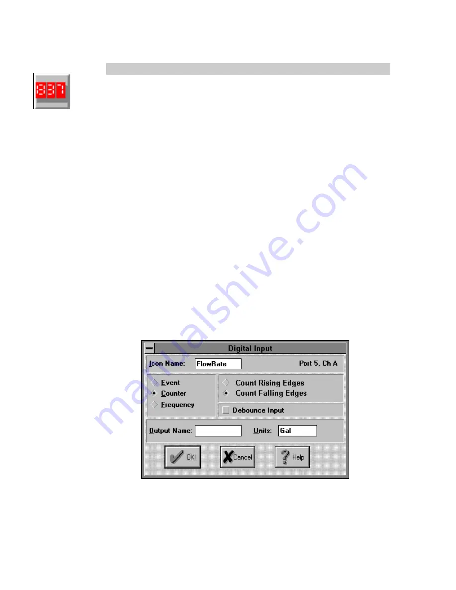
The same dialog is used to configure the four input channels for Event, Frequency, and
Counter functions.
As a COUNTER input, the MLIM-2 channel accumulates counts from a User connected
hardware signal input, then outputs the count to the net when it receives an Update
command. When the count is output, the counter is automatically set back to 0 and
counting resumes.
The MLIM-2 Counter can count pulses received at input rates up to apx 20 Khz. However,
at higher frequencies, the net must be configured to read the counter before it overflows
or the counter will overflow and return to 0 and continue incrementing.
INPUTS:
Hardware:
No signal input shown on Net for Program Net connections. The MLIM-2
Counter function increments its count on received rising or falling edges of
the input signal.
Update:
The accumulated count is output every time an Update command is
received on the Update input. To preclude the loss of data, this Update
command (from a connected Sample Rate Clock ) should be received
before the icon counts to 16,777,216 or the counter will roll-over to 0 and
continue counting, resulting in lost counts.
Enable:
Processing of the icon is allowed when Enable pin is unconnected or
connected
and
the Enable signal is TRUE.
OUTPUTS:
Output Signal:
Data type signal (ie Count totals)
ICON CONFIGURATION DIALOG BOX:
CONFIGURATION OPTIONS:
Icon Name:
Specify the name for the channel. This name will show directly under the
icon within the Program Net. If no name is User provided, the Backplane
Summary of Contents for OMP-MODL
Page 1: ......
Page 9: ...1 INTRODUCTION USING THE MODULOGGER 1 7 13 ...
Page 23: ...2 OMP MODL System Base Using the OMP MODL 2 14 NOTES ...
Page 24: ...2 ModuLogger System Base Using the ModuLogger 2 1 ...
Page 30: ...3 INTERFACE MODULES USING THE OMP MODL 3 6 NOTES ...
Page 70: ...3 INTERFACE MODULES USING THE OMP MODL 3 46 NOTES ...
Page 76: ...3 INTERFACE MODULES USING THE OMP MODL 3 52 NOTES ...
Page 82: ...3 INTERFACE MODULES USING THE OMP MODL 3 58 NOTES ...
Page 83: ...3 INTERFACE MODULES USING THE MODULOGGER 3 1 ...
Page 105: ...5 HYPERCOMM COMMUNICATIONS USING THE OMP MODL 5 18 NOTES ...
Page 106: ...5 HYPERCOMM COMMUNICATIONS USING THE MODULOGGER 5 1 ...
Page 117: ...6 PCMCIA CARD CONFIGURATION AND USE USING THE MODULOGGER 6 1 ...
Page 134: ...7 HYPERNET ICON BASED PROGRAMMING USING THE OMP MODL 7 17 NOTES ...
Page 141: ...8 P P C D U OMP MODL ...
Page 149: ...9 HYPERPLOT GRAPHIC DATA DISPLAY USING THE OMP MODL 9 8 ...
Page 161: ...10 HYPERTRACK REAL TIME DATA DISPLAY USING THE OMP MODL 10 12 NOTES ...
Page 162: ...10 HYPERTRACK REAL TIME DATA DISPLAY USING THE OMP MODL 10 1 ...
Page 163: ...11 APPENDICES USING THE OMP MODL 11 1 11 APPENDICES ...
Page 164: ...11 APPENDICES USING THE OMP MODL 11 2 NOTES ...
Page 270: ...11 APPENDIX A MASTER ICON FILE REFERENCE USING THE OMP MODL 11 108 ...
Page 276: ...11 APPENDIX C HYPERWARE FILE LISTING USING THE OMP MODL 11 114 NOTES ...
Page 278: ...11 APPENDIX C HYPERWARE FILE LISTING USING THE OMP MODL 11 116 NOTES ...
Page 279: ......
Page 282: ...11 APPENDIX E CHANGING THE OMP MODL EPROM USING THE OMP MODL 11 120 NOTES ...
Page 288: ...11 APPENDIX G HYPERNET THEORY OF OPERATION USING THE OMP MODL 11 126 NOTES ...
Page 290: ...11 APPENDIX I RS 232 CABLE PORT AND ADAPTER USING THE OMP MODL 11 128 NOTES ...
Page 297: ...11 APPENDIX K MODEM CONFIGURATION USING THE OMP MODL 11 135 ...


