background image

Section 3 

– Installation 


Page 23 


09/11/2008 REV 0.99 


3.9


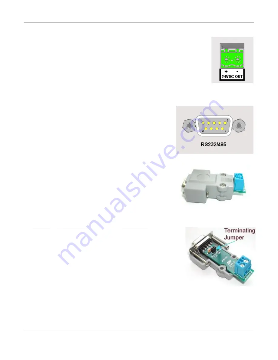
24Vdc Isolated Output (Option) 

The  Isolated  24Vdc  Output  is  an  option  that  provides  24  Volts  DC  @  100  milliamps  to 
power external (current loop) sensors. The output is isolated to 1000 volts from all internal 
voltages and ground. The output is also protected against short circuit. 

The output is polarized and is marked for positive (+) and negative (-). This option is field 
installable. 


3.10


Isolated Serial Interface (Option) 

A standard DB9 Female connector is required for the RS232 to connect 
to  an  IBM  PC  compatible  computer  using  a  null  modem  cable.  The 
RS232 interface can support cable runs up to 50 feet [16 m]. The RS485 
connection  is  via  two  wire  (twisted  pair)  cable  (a  DB9  Female  adapter 
connector is required) and can support cable runs up to 4000 feet [1300 
m]. 

The  RS232  and  RS485  connections  are  mutually  exclusive  and  are 
selected using pin 1 of the DB9 connector 

– see right. 

The  interface  is  isolated  from  internal  circuitry  to  500  volts.  The  RS485 
requires a 120 ohm terminating resistor if it is the last unit on the drop. All 
Serial  Interface  connections  are  made  through  the  DB9  female 
connector.  An  adapter  connector  is  included  that  brings  out  the  RS485 
connections to a set of screw terminals and has the terminating resistor on 
the  board.  The  RS485  connection  is  marked  A  and  B  for  duplex  2  wire 
connection. A is + and B is -. 

If  the  terminating  resistor  is  required  it  is  necessary  to  open  the  adapter 
shell and insert the jumper to enable the termination. 


The connections to the DB9 female connector are as follows: 

DB9 PIN 

CONNECTION   


DIRECTION 


Mode Select (see below) 

In


RxD Receive Data 


In 


TxD Transmit Data 


Out 


DTR Data Terminal Ready 

Out 


Common 


Out 


RTS Request To Send   

Out 


CTS Clear to Send 


In 


RS485 A+ 


Bidirectional 


RS485 B- 


Bidirectional 

 
The mode select pin (pin 1) must be left unconnected for RS232 operation 
or must be grounded (to pin 5) for RS485 communication. Use the provided 
adapter for RS485 communication 

Figure 3-16 

Figure 3-17  Serial I/O 

Fig 3-18  RS485 Adapter 

Fig 3-19  RS485 120 Ohm Jumper 

Summary of Contents for Rercorder RD8300

Page 1: ...www omega com e mail info omega com User sGuide RD8300 Recorder MADE IN Shop online at Forlatestproductmanuals omegamanual info ...

Page 2: ...0800 4 06342 e mail france omega com Germany Austria Germany Austria Germany Austria Germany Austria Germany Austria Daimlerstrasse 26 D 75392 Deckenpfronn Germany Tel 49 07056 3017 FAX 49 07056 8540 Toll Free in Germany 0130 11 21 66 e mail info omega de United Kingdom United Kingdom United Kingdom United Kingdom United Kingdom One Omega Drive River Bend Technology Centre ISO 9002 Certified North...

Page 3: ...r Supply 6 2 4 2 Analog Inputs 6 2 4 3 Input Output Module 7 2 4 4 Computer Interface 7 2 5 Files 8 2 5 1 Configuration Files 8 2 5 2 Data Files 9 2 5 3 Activity Files 9 2 5 4 Miscellaneous Files 9 2 6 Exhibitor Software 9 2 7 QUICK START GUIDE 10 2 8 Keyboarding 11 2 9 Help 11 2 10 Activity Lights 11 2 11 Security 11 2 11 1 User Levels 12 2 11 2 Remote Access Passwords 12 3 0 Installation 13 3 1 ...

Page 4: ... 3 4 Linear Inputs 19 3 4 3 5 Potential Free Contacts 20 3 4 3 6 Frequency 20 3 4 4 Relay Output Contact Input 21 3 5 Ethernet 21 3 6 USB Connection 22 3 7 Audio Connection 22 3 8 Mouse and Keyboard Connection 22 3 9 24Vdc Isolated Output Option 23 3 10 Isolated Serial Interface Option 23 4 0 Fuctional Description 24 4 1 Display Elements 24 4 1 1 Live Display Area 24 4 1 2 Task Bar 24 4 2 Utility ...

Page 5: ...sing Browser Jump To 37 4 14 Browsing Annotations 37 5 0 Recorder Setup 38 5 1 Input Channels 38 5 1 1 Master Channel Setup 38 5 1 2 Channel Setup 39 5 1 3 Channel Type Setup 40 5 1 3 1 Linear Input 40 5 1 3 2 Resistance Input 40 5 1 3 3 Industrial Square Root Extraction 41 5 1 3 4 Thermocouples and RTDs 41 5 1 3 5 Calculated Input 42 5 1 3 6 Conditional Input 44 5 1 3 7 Gated Timer 44 5 1 3 8 Tot...

Page 6: ...7 5 6 4 1 Point type Max Min Average 67 5 6 5 Timed Record 68 5 6 6 Split Files 68 5 6 7 Triggered Record 68 5 6 8 Media Alarm 69 5 7 System Administrative Menu 70 5 7 1 Temperature Compensation 72 5 7 2 System Setup 72 5 7 2 1 NTP Time Server 72 5 7 2 2 Modbus Settings 73 5 7 2 3 Mouse Pointer Enable 73 5 7 2 4 Config Auto Save 73 5 7 2 5 Menu Timeout 73 5 7 2 6 50 60 Hz Filter 73 5 7 2 7 Unit Ta...

Page 7: ...r 90 6 5 2 Remote Control 93 6 5 2 1 Remote Display 93 6 5 2 2 Remote Manager 94 7 0 Instrument Care and Maintentance 95 7 1 Touch Screen 95 7 2 Cleaning Instructions 95 7 3 Calibration 95 7 3 1 Calibrating Linear Voltage Inputs 96 7 3 1 1 Set Channel 96 7 3 1 2 Zero Cal 96 7 3 1 3 Full Cal 96 7 3 1 4 Store Cal 97 7 3 2 Calibrating the RTD Current Source 97 7 3 2 1 Zero Cal RTD 97 7 3 2 2 Current ...

Page 8: ...Microsoft Corporation CompactFlash and CF logo are trademarks of the Compact Flash Association CFA For the purpose of the manual the and symbols will not follow their own trademark names or registered trademark names Company names and Product names mentioned in this manual are trademarks or registered trademarks of their individual owners Symbols One or more of the following symbols may appear on ...

Page 9: ...C 60947 3 A separable coupler which can be disconnected without the use of a tool A separable plug without a locking device to mate with a socket outlet in the building 2 The protective earth terminal must remain connected even if the recorder is isolated from the mains supply if any of the measuring communications or relay terminals are connected to hazardous voltages 3 Whenever it is likely that...

Page 10: ...a large selection of third party Data Access Specification compliant software and the companion Exhibitor Software providing real time data update over Ethernet and off line data analysis The recorder can be set up to send emails in the event of an alarm See Section 4 10 3 Email on Alarm Event for more details The recorder can save data alarms and events to a number of sources The primary storage ...

Page 11: ...rocesses it in real time applying any scaling or linearization as required by user programming and holds it in a buffer for use by the rest of the system This process has the highest priority and runs irrespective of whatever other activity is going on in the recorder Data is fed on demand to the following Data Storage Manager receives data at a rate set by the user for recording to the media The ...

Page 12: ...bove There is a soft master enable switch which allows the user to configure alarms without affecting the actual optional relay contacts The Digital Input Manager is used to define the operation of the optional isolated digital inputs and process these inputs according to the user set conditions when they occur Digital inputs can be used to reset timers or totalizers acknowledge and reset alarms f...

Page 13: ...r is closed and the waterproof lock cover is in place 2 3 1 Display Area The recorder has a VGA color display 320 x 240 pixels and can display 24 million colors The display has a touch screen over it and is fully interactive The screen consists of two distinct areas the task bar with icons along the bottom of the screen and the live display which is that area above the task bar showing the live da...

Page 14: ...refinger and remove To the left of the card slot is a small opening Set back behind this opening is the system reset button Under normal operation there should be no need to use this Using this button may cause loss of data 2 3 3 Status Indicator The status indicator is lit when the unit is powered on and blinks during shut down or when the unit is running off the internal batteries The internal b...

Page 15: ...hown in above On the right is the AC power input socket that takes a standard IEC connector Screw terminals are available as an option as is a DC power supply module To the left is the optional 24 Volt dc output option which provides isolated voltage to power external sensors 100mA Below this is the battery disconnect switch The battery is used to enable the system to shut down correctly and survi...

Page 16: ... of the unit indicated but not shown in Figure 2 4 above Slide the switch toward whichever connector is being used The Type of port selected A or B depends on what is to be connected to it To the left of these connectors are two mini din style connectors The mouse keyboard connector allows the use of an external PS2 PC style mouse directly or a PS2 PC style keyboard using an available adapter boar...

Page 17: ... or loads a configuration using the Configuration Manager the system takes care of the details and defaults to the ConfigFiles directory When saving the configuration the user enters a filename and accepts the entry for example the filename could be pumphouse The Recorder will then create a folder in the ConfigFiles directory called pumphouse_cfg and in this folder it will create the two configura...

Page 18: ...ation together The dat files can be transported or moved using the FTP manager and can be analyzed on the PC using the Exhibitor software 2 5 3 Activity Files The activity files are saved when the Activity Log check box is checked in the User Setup Menu The Activity Logs are stored in the Activity Folder in internal memory SD Card These files are used for FDA 21 CFR Part 11 compliance The files ar...

Page 19: ...oap Plant Boiler This is known as the Unit Tag and is entered in the System Setup window Analog Setup You will then need to set up the analog inputs to meet the requirements of the signals you will be measuring The recorder has universal inputs capable of measuring a variety of signals from millivolts to Volts Current Resistance Thermocouples RTDs and on some channels Frequency All channels can al...

Page 20: ... is available on most set up screens by tapping the help icon shown left on the right of the blue name bar near the bottom of the screen see Figure 2 5 above This will bring up a help text file which deals specifically with the subject at hand The scroll bar at the right of the screen can be used to browse through the file Tap the DONE button to exit 2 10 Activity Lights At the bottom right of the...

Page 21: ...ete activity log can be generated by the accompanying Exhibitor software comparing the two configuration files and all parameters changed can be reported 2 11 2 Remote Access Passwords The user can access the recorder remotely using various methods Each method is protected by a unique password The passwords need to be set up by the Administrator in the System Administrative Menu as follows USB Acc...

Page 22: ... as described in the following section 3 1 4 Equipment Return Before returning a damaged or malfunctioning instrument to the factory for repairs contact the sales organization from which you purchased the instrument A Return Merchandise Authorization number must be obtained from the factory before returning an instrument for any reason 3 1 5 Storage For prolonged storage before installation re pac...

Page 23: ...arked in close proximity to the Recorder and easily accessible to the operator 3 3 Installation The recorder is sized to fit in a standard DIN panel cutout of 5 43 x 5 43 138 mm x 138 mm and requires a minimum of 6 5 188 2 mm behind panel depth not including power and input source cable space needed Actual dimensions are shown below Figure 3 1 Recorder Dimensions in Inches mm WARNING Do not use th...

Page 24: ...d on the enclosure 3 3 1 4 Insert the recorder rear end first into the panel opening from the front of the panel as shown in Figure 3 3 Ensure that the gasket is between the front bezel of the recorder and the front panel 3 3 1 5 With the recorder held firmly in place against the panel install one of the locking bar assemblies by sliding the locking bar notch into the slot on the side or top of th...

Page 25: ...Section 3 Installation Page 16 09 11 2008 REV 0 99 Figure 3 3 Front Panel Insertion Figure 3 4 Rear View Panel Insertion Panel Back Locking Bar Assembly Seal unused slots Panel Front Gasket ...

Page 26: ...n of the plug is connected to a low impedance safety ground earth within the ac power distribution system you are using Always use the recommended mating connector and an approved three wire cable to connect this unit to the ac mains Always provide a low impedance safety ground wire to the ground lug on the rear panel marked Figure 3 5 shows the IEC 320 AC mains connector on the rear of the record...

Page 27: ...ectors on the rear panel Inputs can be mixed in any combination of thermocouple RTD milliamps millivolts volts or contact inputs In addition channels 1 and 6 and optionally 7 and 12 can accept frequency inputs via an additional terminal There is a common ground lug marked with a for connection of signal cable shields or screens COM IN IN CHAN 9 COM IN IN CHAN 8 COM IN IN FIN CHAN 7 CHAN 3 CHAN 2 C...

Page 28: ...ce due to ground loop currents When grounded transducers are used the shield should be grounded at the sensor end only 3 4 3 1 Analog Inputs The Analog Input board can have 6 or 12 channels 12 shown below Each Input is truly differential and has a positive IN and negative IN input and an RTD Common COM for RTD current return and Frequency input Common ONLY Channels 1 and 6 and optionally 7 and 12 ...

Page 29: ...on channels 1 6 7 and 12 only Default input is for 12 to 24V DC 20mA max The inputs can be jumpered internally for 5 to 12V dc See Appendix B for details Figure 3 10 Analog Inputs Wiring Detail CHAN 1 7 FREQUENCY PULSE INPUT CHAN 6 12 FREQUENCY PULSE INPUT THERMOCOUPLE VOLTAGE AND CURRENT RTDs CONTACTS NOTE RESISTOR FOR CURRENT ONLY 50 Ω 0 1 0 5W ...

Page 30: ...is no polarity Maximum switching voltage is 200 Vdc and 0 5 Amp at a Maximum of 10 Watts Voltage x Current 10W per contact The potential free relay contacts are protected internally with 270 volt Metal Oxide Varistors MOVs to prevent contact arcing There are two optically isolated digital inputs which accept 12 to 24 volt DC inputs These can be jumpered internally on the circuit board for 5 to 12 ...

Page 31: ... to the recorders audio lines Connections are as follows Pin Direction Description 1 Out Audio Common 2 In Microphone Input 3 Out Line Output Left 5 Out Line Output Right 4 In Line Input Left 6 In Line Input Right An adapter is available that converts the Mini Din to 3 Standard Phone Jacks for Microphone In Line In and Line Out 3 8 Mouse and Keyboard Connection The keyboard mouse connector is a 6 ...

Page 32: ...e is isolated from internal circuitry to 500 volts The RS485 requires a 120 ohm terminating resistor if it is the last unit on the drop All Serial Interface connections are made through the DB9 female connector An adapter connector is included that brings out the RS485 connections to a set of screw terminals and has the terminating resistor on the board The RS485 connection is marked A and B for d...

Page 33: ...l react to taps on the screen Tapping the Task Bar will cause the live display to move to the next display assuming you have set up more than one in the Rotate List Double tapping the Digital Display or the scale on the Bar Chart and Trends will take you to the widget setup for that particular widget Tapping the bar below the Trend will advance the scale to the next channel Double tapping the actu...

Page 34: ...le alarm tone User must be logged in to use Refer to the Alarms section for more detail When GREEN it indicates that there are no alarms present When AMBER it indicates there are no alarms but the audible Alarm Tone has been muted When RED it indicates there are alarms present OR the alarms have been disabled Record Icon This icon indicates the recorder record mode It changes according to what the...

Page 35: ... of the recorder firmware versions user logged in unit tag and IP Address Display Builder Allows the user to create live displays using widgets Log in required Manager Admin only Details Here Rotate List Allows the user to decide which displays appear on the live display when the task bar is pressed Log in required Details Here Display Utilities Allows the administrator to adjust the display back ...

Page 36: ...txt EventFile txt and LogFile txt The files are encrypted but can be read by the accompanying software The files may also be saved to a specific location using the Save As button Admin only The files can be cleared using the Clear button Admin only The files should be cleared periodically for the sake of efficiency and space 4 4 Record Session A record session commences once a file name has been d...

Page 37: ... file browse window will pop up showing the configuration files available Select the configuration you want by tapping on it and press okay Note This will load the new config file and the recorder will restart The old configuration settings will be overwritten Save This enables the current settings to be written out to the existing config xml the file will be overwritten or you can assign a new na...

Page 38: ...s To This is the recipient s email address From This is where you enter your name or anything you want to appear in the email From field Note The To and From entered here override the settings in the System Setup Subject Enter text to appear in the email Subject field Attachment You can attach a file to be sent along with the email Tap the browse icon and a file browse window will pop up Browse to...

Page 39: ...rd box if you wish to change your password To Log Out tap the Log In icon and you will be asked if you want to log out Tap the Yes button Logging in or out is recorded in the Activity Log 4 8 Display Utilities The Display Utility menu allows the user to control the display brightness and background color Enter this dialog by tapping the icon shown left in the System Utility Menu 4 8 1 Display Brig...

Page 40: ...cel button X 4 10 Special Events There are several Special Events that can be programmed into the unit These are dealt with here 4 10 1 Record on Alarm The recorder can be set up to record on an alarm condition This requires setting the alarm and enabling the record option The Channel and Master enable boxes must be checked The record menu must be set up to record on alarm and the unit must be set...

Page 41: ... has been setup There must be a functional Ethernet connection Alarm Setup Notify is checked Alarm Enable is checked Alarm Master Setup Channel Enable checked Master Enable checked Notify Enable checked Alarm The specified alarm must be in an alarm condition 4 11 Turning the unit off When power is removed from the unit it does not turn off immediately There is a battery backup in the power supply ...

Page 42: ...ction 4 12 2 Tap this icon to select the color of the pen to be used to write on the screen The block below the icon shows the current pen color black Tap this Place Text icon to place the text in the text dialog box It is necessary to first enter text in the box which contains the words JACK HIT RESET in Figure 4 12 2 After tapping the icon tap the position on the screen where you want the text t...

Page 43: ...is you need to tap the browse button left on the bottom right of the live trend display as shown on the right This will bring up the Browse Display window See Figure 4 13 2 which essentially freezes the current display live data is still updating in the background and retrieves data from a buffer holding the historic data through the time the browse button was tapped Note the envelope icon on the ...

Page 44: ...Bar is used to scroll back and forth through the data buffer Sliding to the left brings up older data sliding to the right brings up newer data To move press the slider with the stylus or finger and drag or tap the bar to the left or right of the slider Exit Returns to live data Note The browser will always be in the form of a horizontal trend even if the live trend is vertical When in the browser...

Page 45: ... 13 7 If you removed renamed or deleted the bmp file you will get an error message When you are done viewing the memo tap the OK button On the bitmap tap the check mark Done button If the memo or bitmap was attached while recording a file these items will be available for review on the PC software 4 13 3 Using the Cursor Available only in the Browse mode Pressing the cursor button will bring up a ...

Page 46: ...trend window by double tapping anywhere on the trend This will bring up the Browse Annotate selection box shown left The drop down menu shows the times of all attached memos or bitmaps in the buffer with the latest one first Select the time of the attachment you wish to view then press the attachment envelope button The memo or bitmap will be displayed as shown in View Memos above Figure 3 14 1 Li...

Page 47: ...ctly associated with live inputs through the computational and conditional options 5 1 1 Master Channel Setup The Master Channel Setup window is a one stop shop to quickly set up all the channels or get a general overview of channel setup If passwords are enabled the user has to log in as Administrator in order to access NOTE You cannot use this option if the unit is in the record mode you need to...

Page 48: ...p Channel Type Setup Use this button to further set up the channel type selected See Channel Type Setup Point Tag Enter up to nine alphanumeric characters to uniquely identify the channel Up to 8 characters can be entered Eng units Enter up to eight alphanumeric characters to indicate the engineering units for the channel Up to 7 characters can be entered Note Setting up the channel will default t...

Page 49: ...en the input is 1 volt the output will read 1 If the Output HIGH was set to 100 then the output would be 0 to 100 for an input of 0 to 1V The input is effectively multiplied by the Output High Input High Span The span is a correction value that is multiplied by the full scale input and applied linearly across the range The default is 1 Offset The offset is an adder subtractor that is added or subt...

Page 50: ...scale which is equal to 0 5 Square Root of 0 5 0 707 Actual value displayed is 0 707 x 1000 707 GPM with Decimal fix of 0 The setup is the same as it is for the Linear input in Section 5 1 3 1 5 1 3 4 Thermocouples and RTDs Thermocouple and RTD setup is similar to the Linear setup except that the Input and Output scaling cannot be altered Note that the displayed scales can be set independently for...

Page 51: ...is equivalent to 3 41592 Functions This allows the user to define up to six functions for use in the calculations To set up a function check the Define box then press the Function button say F1 The input line will show F1 continue to enter your formula using the available buttons The and buttons will move the cursor the Delete button will delete the character to the left of the cursor and Clear bu...

Page 52: ... max min avg values will be reset by an external event via the digital inputs Note an optional digital I O card must be present in the system AND the designated input must be input is enabled The digital input needs to be programmed as a MinMaxAvg type Reset Intrvl This is the Reset Interval This is the time in days hours minutes and seconds between timer resets when Auto Reset is checked In the e...

Page 53: ...le of Figure 5 8 Channel 13 is being programmed to indicate zero to 100 for a 4 20 milliamp input on Channel 1 with any input less than 4 milliamps showing zero 5 1 3 7 Gated Timer The Gated timer Calculated point type allows a timer measuring in seconds to be controlled by a gate from a logic point For example if a point is measuring temperature and you wanted to know the total amount of time the...

Page 54: ...ch time the timer resets Power Up Reset When this box is checked the Totalizer will start from zero each time the unit powers up otherwise it will carry on where it left of before 5 1 3 8 Totalizer The Totalize calculation keeps a running total of the value of a base point sampled at a programmed rate This will continue until the programmed reset interval time is reached at which time the value is...

Page 55: ... the drop down menu should be set up for the correct input and in the correct units Total Reset on Alarm If checked the Total will be reset by the Alarm condition selected In this case when Channel 1 Alarm 1 is active the Total will be reset 5 1 3 9 Frequency Pulse Count Channels 1 6 7 and 12 can be used to measure frequency Frequency is applied to a separate isolated input Inputs are TTL compatib...

Page 56: ...ox is checked then the totals will reset at the reset interval once the start time Reset Sync has been met Ext Reset Enable This is the External Reset If this box is checked the count will be reset by an external event via the digital inputs Note an optional digital I O card must be present in the system AND the designated input must be programmed as a count reset for this to work Reset Point This...

Page 57: ...l is reset the information will be appended to the alarm event log time and total Total Reset on Alarm If checked the Total will be reset by the Alarm condition selected In this case when Channel 1 Alarm 1 is active the Total will be reset Apply Save the values and exit Cancel Exit without making any changes ...

Page 58: ...splay Builder icon to launch the Display Builder dialog window shown right The Display Builder consists of a palette on which the user can place widgets to create a display The palette is a grid of blocks 6 across by 8 down Each widget is a finite size consisting of 2 or more blocks see below for details The buttons to the right allow the user to select the widget types while the drop down selecti...

Page 59: ...etup information for Digital Display Bar Charts or Trends below Widgets already placed can be moved or deleted The display can be named or renamed and saved and the whole process can be aborted by pressing the Cancel button 5 2 2 Editing Once widgets are placed the following buttons can be used to edit the display Delete Will delete a widget Press the Delete button then tap the widget you want to ...

Page 60: ... the example is the default display that will show when the unit is powered up Subsequent displays in the list will show each time the Task Bar is pressed in the order listed To remove all displays from the Rotate List press the Double Right arrow button To remove a display from the Rotate List highlight it then press the Right arrow button To add a display to the Rotate List highlight it in the D...

Page 61: ...apping the Digital Display widget on the screen The dialog box shows the Channel Number 2 and the Channel Type Digital Readout The user can use this dialog to change appearance parameters of the Digital Display Widget or can proceed beyond to fully set up or edit the channel information Channel Shows the current Channel assigned to the widget The user can change the assignment by selecting a diffe...

Page 62: ...on will DELETE the Digital Display Widget This will remove it from the display 5 3 1 2 Displaying Min Max or Average Values The Digital Display widgets show the instantaneous channel value but can be changed at any time to display minimum maximum or average values To change the reading double tap in the lower line of the digital display widget indicated right This will pop up a drop down menu that...

Page 63: ... any time by double tapping the scale on the bar graph widget on the screen The dialog box shows the Channel Number 2 and the Channel Type Horizontal BAR Full The user can use this window to change appearance parameters of the Bar Graph widget or can proceed beyond to fully set up or edit the channel information Channel Shows the current Channel assigned to the widget The user can change the assig...

Page 64: ...on Alarms When the Active box is checked the alarms are active for this Channel 2 provided the Master Enable is set when not checked the alarms are deactivated for this channel Pressing the Alarms button opens the Alarm Setup dialog window This allows changes to be made to the channel alarm settings which will affect ALL widgets using this channel This is a protected option Apply Pressing this but...

Page 65: ...ble and what the engineering units are The Browse button on the right of the name bar below the trend allows the user to go to the trend browse screen Here the user can scroll through historic data zoom measure annotate and save or print images of the trend Trends can have up to 18 channels on a display although this could be extremely cluttered Since it is possible to create multiple trend displa...

Page 66: ...ultiple channel information as well as general Trend display information is set up on this screen Enable If this box is checked the Trend is enabled if this box is unchecked the Trend is disabled and will indicate OFF in the Trend Name area Update This is the screen update rate in seconds and determines the speed of the Trends A new point is added and the trend advances by 1 pixel each Update Rate...

Page 67: ...spective box and entering the value required Active If this box is checked the channel will appear on the Trend if this box is unchecked the channel will not be displayed on the Trend Setup Pressing this button opens the Channel Setup window This allows changes to be made to the channel settings which will affect ALL trends and widgets using this channel Alarms Enable alarms for this channel if ch...

Page 68: ...et alarm if condition is False or Closed as defined Conditional inputs and Dry Contacts ONLY If you try to program an alarm with an illegal condition for example setting a Linear Voltage input alarm to Type False you will get an error The Alarm status is shown in the Task Bar at the bottom of the screen This icon also doubles as the Alarm Acknowledge button This icon changes color as shown below N...

Page 69: ...utton Setup Proceed to set up the individual alarms see below Channel Below the overview is the Channel selection drop down box This shows the current alarm setup and allows the user to select any of the 18 channels If you enter the setup from a specific channel you cannot change the channel Channel Enable When checked the alarms that are enabled for the channel will be active When unchecked alarm...

Page 70: ...is is the value in the same engineering units as the channel that the alarm condition is tested against also known as the threshold In the above example when the input is greater than high alarm 350 the alarm will be true See the definition of other alarm conditions above Dead band This value is the hysteresis for the alarm Once the alarm is true active this value is subtracted from the setpoint a...

Page 71: ...of the digital outputs is indicated by the icon on the Task Bar which also doubles as the Alarm Reset button The Alarm Reset button will drop out any contacts that are latched and no longer in alarm or any alarm that is set to drop out on reset The status is indicated as follows Relay outputs all reset safe condition One or more relay outputs active alarm condition The relay outputs can be configu...

Page 72: ... If a Digital IO card is not present in the recorder or there are less than 12 relays on it you will not be able to check the enable box of relays not present in the system Manual These buttons enable the user to override the current status of the relay outputs in real time Set activates the relay Reset deactivates the relay The icon on the button changes to indicate the current status of the outp...

Page 73: ...nowledge functions as the Alarm Acknowledge button in parallel with the screen icon This will silence the local recorder alarm tone Alm Rst Alarm Reset functions as the Alarm Reset button in parallel with the screen icon to drop out any eligible relay outputs Alm Both Functions as both the Alarm Acknowledge and Alarm Reset button equivalent to pushing one then the other Event Forces an event in th...

Page 74: ... ALL external events are ignored This allows setup without the possibility of an external event triggering the system unexpectedly It can also disable external events temporarily without having to reprogram inputs Print on Demand This button brings up the channel selector which allows selection of which channels will have a status printout when the input is active The printout is serial ASCII and ...

Page 75: ...t to stop recording If the recorder is not currently recording the Record Setup icon will have a green circle in the bottom left hand corner as shown left When this icon is pressed a Record dialog box will pop up shown right The options are Note If recording has not been set up you cannot start to record If the unit is recording the dialog box will require that you stop recording Access to the Rec...

Page 76: ...nds drop down lists The fastest sample rate is 10 times a second 0 1 seconds the slowest rate is once a day The example here shows a sample interval of once per minute Note file size is proportional to sample rate the faster the sample rate the bigger the file 5 6 4 What to Record Select what to record and how Points is the actual data check the box to record the actual point data Alarms will reco...

Page 77: ...select NEVER 5 6 7 Triggered Record There are various options that will start a recording other than manually by the operator The alarm triggered events are listed below In order to enable these events three steps are required Enable the event in this Record Setup dialog 1 Set up the record trigger sources alarms or digital inputs External Trigger in their respective setup dialogs or time in this ...

Page 78: ... menu from 60 to 100 Event Message Enter a message in the entry box up to a maximum of 20 characters which will be appended to the alarm event log message if the Print check box is checked This message will also be appended to the email if the notify box is checked see above Audio File The recorder can play a wav file PCM type only instead of the standard alarm sound These audio files must be save...

Page 79: ...mpensation Details Here Touch Screen Calibration Allows the administrator to calibrate the touch screen Tap the X until it disappears then tap anywhere on the screen to exit System Setup Allows the administrator to set up system parameters such as device name and email information Details Here Date Time Setup Allows the administrator to set the unit s date and time parameters Details Here User Adm...

Page 80: ...dministrator to set the password for USB connection via ActiveSync Detail Here Save or Clear Registry Allows the administrator to save or clear the system registry Details Here Load Language Allows the administrator to load alternate languages provided the language files are available Details Here Reflash Firmware Allows the system firmware to be updated This is potentially destructive operation i...

Page 81: ...grees in 0 5 increments in either Centigrade if the Deg F checkbox is unchecked or Fahrenheit if the Deg F checkbox is checked Update button make the adjustment Done button exits the window 5 7 2 System Setup The System Setup allows the administrator to adjust some basic settings of the unit like Unit Tag This feature is entered from the system admin menu by pressing the icon shown right This will...

Page 82: ... 60 Hz Filter In noisy environments the AC mains frequency interference can affect the readings on the most sensitive millivolt ranges when running at sample rates asynchronous to the AC mains frequency If the sample rate can be made to run synchronously with the AC mains frequency the noise effect of that frequency is minimized because the recorder has differential inputs and samples at the same ...

Page 83: ...ed in the User Management dialog window entered from the system admin menu by pressing the icon shown left If security is enabled only the Administrator can access this function The Password Management dialog window can be used to edit existing users or create new users Existing users are shown in the user list Security Enable If this box is checked security is enabled and active If unchecked secu...

Page 84: ...ng the Explorer icon shown right Tap the icon to bring up the browser screen shown below Note the screen you see may differ depending on how you have selected the View The window shows all folders and media devices in the recorder The internal memory is the SD Card There may also be icons for the USB HD Hard Drive or the CF Card Note Do not move or delete any system files or folders as this will a...

Page 85: ...own left As a minimum there needs to be a user named Admin for remote administration Add remote users as needed by selecting Authenticate users locally and tapping the Add button This will pop up a Dialog box shown below where you can enter Username and Passwords If there is no keypad it needs to be launched manually Do this by tapping the very bottom of the screen which will bring up the Task Bar...

Page 86: ...o authenticate to the mail server If you are going to use the smtp address smtp unlimitedmail org you will need to setup an account at www unlimitedmail org SMTP password This is the user password needed to authenticate to the mail server Once the changes have been made press the accept button to exit or the cancel button to quit without saving the changes 5 7 9 Set ActiveSync Password This allows...

Page 87: ...ed to be cleared if upgrading the firmware This feature is entered from the system admin menu by pressing the icon shown right This will bring up the dialog box shown on the left The user has three choices The top button will save the registry settings to system nonvolatile memory The middle button will clear the registry and set it to factory default values Note Do not clear the registry unless r...

Page 88: ...corder will change to the new language on the fly The default language is English 5 7 12 System ReFlash This option allows the administrator to upgrade the system firmware Once started this operation cannot be reversed Choosing to proceed will require a system reset even if you cancel the operation DO NOT RESET the unit DO NOT REMOVE POWER and DO NOT PRESS THE ABORT BUTTON while this operation is ...

Page 89: ...into the FileName space Press the Accept Button This will replace the entire contents of non volatile memory with a new image This is equivalent to formatting the hard drive on your PC and reinstalling everything DO NOT RESET and DO NOT REMOVE POWER while this operation is in process Once you select this option a file browse window will pop up Navigate to the file NK BIN and press okay A window wi...

Page 90: ...Server Functions Each application that accesses the recorder has its own unique settings so as to not run afoul of Windows Security settings firewalls etc These are dealt with below The available Exhibitor software is an extremely versatile program that supports the recorder and can replay recorded data files in various formats export to Excel view and save real time data upload and download files...

Page 91: ...e engineering units Above to the right of each panel display is the physical channel number In the event that a channel is in Alarm this will be shown in the upper left in large red letters as in the case of Channel 2 The live data updates every 3 to 5 seconds There are a number of buttons below the live data display Chan 7 12 and Chan 1 12 show those channels 7 to 12 or all channels 1 to 12 View ...

Page 92: ...me depending on your connection speed Once downloaded you may get several warning notices or security warnings You need to accept or run the programs in order for the site to operate properly Once the program has been downloaded and installed you should not see these messages the next time you run the web browser If installed correctly or if it already exists you will see a popup box asking for a ...

Page 93: ...e IP address of the connected recorder as heading 192 168 1 193 in this example The current path points to the folder 1 7 2008 on the Compact Flash Card CF Card Note that the recorder has a device structure rather than drives i e CF Card and USB HD rather than D and E The file icon to the right of the path is to go up in the directory tree 5 Remote file listing Displays files and child folders on ...

Page 94: ...r allows for file manipulation between the local PC computer and the remote recorder It functions much like Windows Explorer TM and allows files to be uploaded or downloaded between devices allows files to be renamed moved copied and deleted This program limits access to the certain folders and all media in the recorder to prevent accidental deletion of system files that could stop the recorder fr...

Page 95: ...LCs DCSs and other control devices to HMIs and other display clients The recorder is compliant with OPC Data Access 3 0 2 0 and 1 0a standards and also supports OPC Security 1 0 The OPC standard is supported by the associated software suite available for PC which interfaces to the recorder to provide remote real time data access as well as other third party OPC software clients Refer to the Exhibi...

Page 96: ...gers in the form of two bytes as follows Low Byte Bits 0 through 7 When the bit is a 1 the condition is true There is one register for each point or channel and the registers start at number 3056 So Register no 3056 is Channel 1 status Register 3057 is Channel 2 status through Register 3071 which is Channel 18 status These Registers are read only and are accessed using Function 4 6 3 2 2 Modbus Da...

Page 97: ...d 4366 Point 3 Data High Word 4384 Point 12 Data High Word 4367 Point 4 Data Low Word 4385 Point 13 Data Low Word 4368 Point 4 Data High Word 4386 Point 13 Data High Word 4369 Point 5 Data Low Word 4387 Point 14 Data Low Word 4370 Point 5 Data High Word 4388 Point 14 Data High Word 4371 Point 6 Data Low Word 4389 Point 15 Data Low Word 4372 Point 6 Data High Word 4390 Point 15 Data High Word 4373 ...

Page 98: ...icrosoft s ActiveSync is installed and running If it is installed the icon will be visible on the bottom right of the screen as shown left Once the recorder is plugged into the USB port it should be recognized as a Microsoft USB Sync Device and ActiveSync should launch automatically If a password has been set you will be asked for this password Enter the required password and ActiveSync will show ...

Page 99: ... 5 Recorder Setup Program 6 5 1 FTP Manager FTP is short for File Transfer Protocol a standard for file transfer over the internet The FTP manager is a standalone file manager for uploading and downloading files from remote recorders It is installed from the installation disk that came with the recorder Refer to Fig 6 5 above Click the FTP Manager Setup button This will launch the installer Follow...

Page 100: ...u are using the world wide web you will need to know the real address of your firewall router which needs to be set up for port forwarding to the recorder IP address You also need the User Name and Password The program remembers User Names and IP addresses and you can use the drop down menu to select previous entries Once set up you need to connect to establish a link to the recorder See 5 below 2...

Page 101: ...computer and the remote recorder It functions much like Windows Explorer TM and allows files to be uploaded or downloaded between devices allows files to be renamed moved copied and deleted Proceed with CAUTION to prevent accidental deletion of system files that could stop the recorder from operating Once the program is launched enter the IP Address of the recorder or select it if it has already b...

Page 102: ...is launches the program window as shown below Select an IP Address from the pull down menu or add a new one by clicking the ADD Recorder Icon shown right This will pop up a form to enter IP Address Description and User name Once this is added click the ADD button to close Enter the password which is never stored and then press the Connect Icon This will launch a separate window and make connection...

Page 103: ...m the pull down menu or add a new one by clicking the ADD Recorder Icon shown right This will pop up a form shown left to enter IP Address Description and User name Once this is added click the ADD button to close Enter the password which is never stored and then press the Connect Icon right If the user name and password is correct and the recorder is accessible an image of the recorder screen wil...

Page 104: ... with an accuracy at least 10 times greater than the function you are calibrating See Specifications Note Altering the calibration will affect the operation of the unit These functions should only be performed by qualified personnel If security is enabled access is restricted to Administrators only You will need a voltage calibrator capable of generating the voltages indicated below a 250 ohm 0 05...

Page 105: ...ibrated from the drop down menus and press the Set Chan button The Live Data window will show the current value from the connected source and a Channel has been set successfully popup will appear Press OK in the top right corner 7 3 1 2 Zero Cal Select the Zero Cal function from the Calibration Function drop down menu Apply 0 Volts Shorting jumper or set Calibrator to 0V to the channel selected in...

Page 106: ...ng jumper into the selected channel and press the Calibrate button On completion of the step you will get a Calibration Function OK popup dialog Press OK in the top right corner Repeat 6 3 2 2 and 6 3 2 3 above for each RTD channel remember to move the shorting block to the respective channel Once all the required ranges are zeroed select Store Cal from the Calibration Function drop down menu and ...

Page 107: ...lected above with the positive signal going to Fin and the ground to COM See Section 2 4 3 6 for connection detail Press the Calibrate button On completion of the step you will get a Calibration Function OK popup dialog Press OK in the top right corner Select Store Cal from the Calibration Function drop down menu and press the Calibrate button Accept the Calibration Function OK popup dialog In the...

Page 108: ...urvive brownouts and short blackouts 20 seconds Data retention time without power 3 months Power Output Optional isolated 24Vdc 100mA output ANALOG INPUTS Number of Inputs 6 or 12 direct inputs plus 6 additional calculated channels Input Resolution 0 0015 of full scale 16 bit unless otherwise stated Input Impedance 1megohm Maximum Input 50 Vdc Isolation Installation category II Pollution Degree 2 ...

Page 109: ...F S 50 to 1768 C 3 C 58 to 3200 F 6 F B 0 to 1820 C 4 C 32 to 3300 F 7 F Reference junction compensation accuracy 0 5 C 0 C to 50 C RTD Base accuracy 0 2 or 0 5 C 1 F Resolution 0 1 C 2 or 3 wire connection Cable compensation to 50 Ohm Open and short circuit detection 10 ohm Cu 70 to 170 C 94 to 338 F 100 ohm Pt 385 220 to 850 C 364 to 1560 F 100 ohm Pt 392 180 to 820 C 292 to 1500 F 200 ohm Pt 38...

Page 110: ...rver Modbus Over Ethernet Server Serial Option Isolated RS485 RS232 Modbus Interface INPUT OUTPUT OPTION Outputs Optional Up to 12 x Relay out Form A normally open SPST contacts rated at 200Vdc Current 0 5A Max Power 10 watt MAX Inputs Up to 6 optically isolated inputs 5 to 12 Vdc or 12 to 24Vdc 20mA User Selectable DESIGN ATTRIBUTES Operating Range 0 C to 50 C 10 to 80 RH Protection IP65 when mou...

Page 111: ...ws marked A in Figure B 1 and gently pull the module from the enclosure Once the module is removed identify the jumpers as shown in Fig B 2 Note that 6 channel units will not have the daughter board sitting on top of the main board The jumper locations are as follows Bottom Board P4 Channel 6 P5 Channel 1 Top Board if present P4 Channel 12 P5 Channel 7 Fig B 3 shows the jumper detail Jumpers are s...

Page 112: ... that the rear panel is loose and not connected to the circuit board Once the module is removed identify the jumpers as shown in Fig B 4 Note that there could be up to 6 jumpers present The jumper locations are as follows 2 Input Board P2 Input 1 P3 Input 2 Jumpers correspond to inputs from right to left when looking at the terminal block side of the board Jumpers are shown in position 1 2 The lin...

Page 113: ...ty or otherwise shall not exceed the purchase price of the component upon which liability is based In no event shall OMEGA be liable for consequential incidental or special damages CONDITIONS Equipment sold by OMEGA is not intended to be used nor shall it be used 1 as a Basic Component under 10 CFR 21 NRC used in or with any nuclear installation or activity or 2 in medical applications or used on ...

Page 114: ...locity Indicators Turbine Paddlewheel Systems Totalizers Batch Controllers pH CONDUCTIVITY pH Electrodes Testers Accessories Benchtop Laboratory Meters Controllers Calibrators Simulators Pumps Industrial pH Conductivity Equipment DATA ACQUISITION Data Acquisition Engineering Software Communications Based Acquisition Systems Plug in Cards for Apple IBM Compatibles Datalogging Systems Recorders Prin...

Reviews: