background image


Date  29/6/2021 

Document number  921100409_09_002 

Page  65 of 73 


65 / 73 


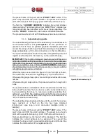
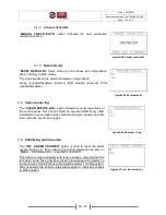
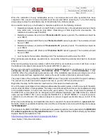
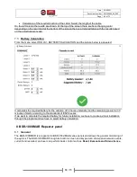
When the BSR-100X/MAR control panel is detected, the message “Ready” will be displayed on the bottom 
line  of  the  “

Synchronize  with  Panel  window

”  To  receive  control  panel  configuration  file,  click  on 

Receive

” button. When the progress bar is filled, the window will close automatically. 

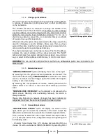
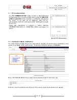
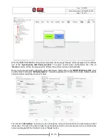
Now you can proceed with configuring panel parameters. Right click on the “

BSR-100X Panel SN:

” entry 

on left column and select “

Edit parameters

”. A window appears with 5 tabs that include multiple options 

and parameters regarding the panel’s data. 


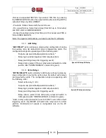
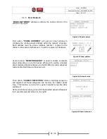
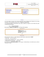
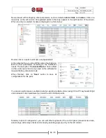
The first tab “

Information

” is where you can change the name of the panel and the technician’s contact 

information. The rest of the tabs include the same options which can be accessed via the control panel’s 
screen and keypad. When finished, click on “

Save

” button. 

Summary of Contents for BSR-100 MAR Series

Page 1: ...BSR 1000 MAR BSR 1001 MAR BSR 1002 MAR BSR 1004 MAR Analogue Addressable Fire Alarm Panel 1 2 and 4 loops Installation Programming Operation WARNING READ THIS MANUAL PRIOR TO ANY INSTALLATION OR USE...

Page 2: ...7 3 Information 14 3 User s Menu 19 3 1 Enable Disable segments 21 3 2 Delays Menu 22 3 3 Set Date Time 22 3 4 Backlight mode 23 3 5 Change user s code 23 3 6 PC Communication 24 3 7 Operating via PC...

Page 3: ...ction 50 5 3 3 Autoaddressing points 51 5 3 4 Change point address 52 5 3 5 General resound 52 5 3 6 Conventional sirens 52 5 3 7 AUX Relay 53 5 3 8 Extra Relays 53 5 3 9 Panel Network 54 5 3 10 Loops...

Page 4: ...tion 67 7 3 Battery Calculation 68 8 BSR 1000 MAR Repeater panel 68 8 1 General 68 8 2 Functions 69 8 3 Installation 69 8 4 Wiring 69 8 5 Setup repeater network 69 8 5 1 Setup repeater address 69 8 5...

Page 5: ...shall be used for cable selection according to your installation size All features and indications are in accordance with European standards 54 2 and 54 4 The BSR 100X MAR series Analogue Addressable...

Page 6: ...rmation regarding the fire detection system state The LED indicators provide general information e g if there is any alarm the General Alarm LEDs are lit while more detailed information is displayed o...

Page 7: ...rm outputs BUZZER SILENCE Mutes unmutes audible buzzer LAMP TEST Turns on all LED indicators for 5 seconds to visually inspect for functionality OVERRIDE DELAYS Immediately activates all alarm outputs...

Page 8: ...emporarily deactivated during alarm state POWER green Mains power connection indication steady lit ok blinking power down PREALARM yellow Prealarm detected TEST yellow The system or part of it is unde...

Page 9: ...s of the control panel according to the description and are yellow Figure1 4 LED Indicators below the screen GENERAL FAULT General panel fault SYSTEM FAULT System fault hardware SUPPLY FAULT Power fai...

Page 10: ...lowing information appears when available alternating every 3 seconds The control panel address and the name of it when panel network is enabled The number of the segments under test if any The number...

Page 11: ...e buzzer until a new event appears Pressing SIREN SILENCE key will deactivate all sirens as long as all other output relays that are set to behave respectively under silence command To view all curren...

Page 12: ...ll be activated instantly bypassing all user programmed delays VIEW ALARMS In alarm state if this key is pressed all current alarms are displayed More details are provided in the next paragraph VIEW F...

Page 13: ...ecord similar to the figures 2 6 Events menu on the right The figures are samples of an information event and of a fault event The first line indicates GENERAL for information events FAULT for fault e...

Page 14: ...PLY shows input battery and charging voltage Figure2 9 Panel power supply ALARM COUNTER option displays the total number of alarms recorded in accordance to EN 54 2 Figure2 10 Alarms counter The TESTS...

Page 15: ...zones that are set in test mode and are also in alarm state This option is meant to be used during maintenance Figure2 15 Alarms in test zones By selecting the POINTS option in the information menu t...

Page 16: ...CE command is given Please note that RELAY 1 FAULT and RELAY 2 ALARM are not editable by user Only RELAY 3 AUX is editable n terms of functionality mode initial state logic delay and silence Navigate...

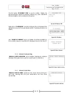
Page 17: ...nel editable via PC software or web interface the network address of the panel and its serial number Figure2 23 Network panels By selecting ETHERNET ADAPTOR option the screen on the right appears When...

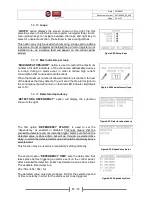
Page 18: ...panel for the CPU and the loop circuits The last line also displays the panel s serial number Note On the screen it is only displayed the firmware for the installed loops e g On the right the screen d...

Page 19: ...onitor figure 4 1 Figure3 1 Main Menu Then select USER MENU and click Enter A code is required for level 2 access Therefore only authorized users will be able to do any adjustments at this level Figur...

Page 20: ...agram In this menu the following basic functions can be done RESET the system clears current alarms prealarms and faults SIREN SILENCE in case of an alarm event to mute audible alarm SIREN RESOUND to...

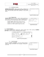
Page 21: ...zone ALL POINTS all loop devices points except sirens POINTS single loop device point except sirens the panel asks for loop and address of the point ALL SIRENS all conventional and addressable sirens...

Page 22: ...KING DAYS set the DAY mode days select day with up down keys and enable disable with right key then enter to save setting Monday to Friday by default WORKING HOURS set the working hours from to 06 00...

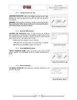
Page 23: ...NG will turn off backlight at any state after 1 minute of inactivity The second option BATTERY SAVING will only turn off backlight while on battery power mains interruption after 1 minute of inactivit...

Page 24: ...p event logs keep a record of current configuration as a backup or to gather and send useful data to manufacturer in terms of troubleshooting When selected a confirmation message as the screen on the...

Page 25: ...omputer s network settings must be properly adjusted All the settings must be done by the building s network administrator Open a web browser and type the panel s IP address to the URL box e g 10 0 9...

Page 26: ...nformational options These options are described below 3 7 4 1 Information Panel This option will display the page below with the most significant data of the control panel hardware based 3 7 4 2 Info...

Page 27: ...hem 3 7 4 5 Information Points This option will open the page below On the input boxes you can enter the point s loop and address By clicking OK the information of the selected point will be displayed...

Page 28: ...extra relays settings Extra relays belong to peripheral equipment and are not pre installed in the control panel 3 7 4 8 Information Conventional Sirens This page displays all settings for the conven...

Page 29: ...the high capacity of recorded events 7k the events are divided into pages 3 7 6 User s menu By selecting USER MENU the systems asks for user code access level 2 Enter the user s code and click SEND I...

Page 30: ...r supply is rated at 220 240V AC 50 60Hz being a Class I product for safety and operation reasons the corresponding terminal contact with the Protective Earth marking inside the device must be connect...

Page 31: ...a MODBUS adaptor at left side optional There is also a Dip switch selector at the bottom right side of the board which is used to grand access level 4 for specific functions At the bottom left side i...

Page 32: ...her supply lines should cross the wall behind the panel except the panels own power supply The control panel s placement must be to a visible and accessible area to the ship attendant and fire safety...

Page 33: ...completed 3 The mains power fuse of the panel is located in the power supply unit rated 4A 250V Fast TR5 non replaceable 4 The battery protection fuse is self restoring 900mA rated soldered on the mai...

Page 34: ...nect the rest of the poles in between negative pole of the first battery to the positive pole of the second battery On the following figure 4 4 the batteries connection diagram is depicted In case of...

Page 35: ...st use a separate cable with a 2 core shielded cable These connections refer to conventional siren outputs 24VM output 24VP output and loop connection terminals Don t use the same cable for multiple l...

Page 36: ...rt circuit links L to LF and L to LF In order to connect one or more devices to the loop output remove the 2 short circuit links entirely All loop connections are similar A maximum number of 150 devic...

Page 37: ...Date 29 6 2021 Document number 921100409_09_002 Page 37 of 73 37 73 Figure 4 6 Detector base connections BSR 6155 MAR BSR 6160 MAR and BSR 6157 MAR...

Page 38: ...ment number 921100409_09_002 Page 38 of 73 38 73 Figure 4 7 Connecting the manual call point MCP BSR 5136 MAR Figure 4 8 Connecting addressable siren BSR 5132 MAR Figure 4 9 Connection of input output...

Page 39: ...e resistor must remain on the terminal When sirens are connected to the output the resistor must be removed and placed on the last siren as shown on the figure 4 10 All four circuit connections are id...

Page 40: ...tion of a network of panels Figure4 11 Panel network connection Be advised the RS 485 requires 120 resistors on both ends To the panels that are located on the edge of the network a jumper connector m...

Page 41: ...Date 29 6 2021 Document number 921100409_09_002 Page 41 of 73 41 73 4 6 General connections diagram A theoretical general connections diagram is depicted below Figure4 12 General connections diagram...

Page 42: ...FAULT Relay Potential free relay contacts that are triggered during a fault event C NC contact circuit active when on fault 30VDC 3A max AUX Relay Potential free relay contacts with a programmable out...

Page 43: ...ble printer option While the thermal printer is connected and enabled all new events recorded will be printed on paper MODBUS To enable MODBUS communication between the control panel and a Building Mo...

Page 44: ...which can be granted with hardware access dipswitch selector behind the door To enter Technician menu while on home screen press Enter key once to enter main menu Figure5 1 Main menu Then select TECH...

Page 45: ...Date 29 6 2021 Document number 921100409_09_002 Page 45 of 73 45 73 Figure5 3 Technician menu diagram In the following sections a detailed description for every available option appears...

Page 46: ...in test Next the control panel asks for siren mode enabled or disabled By enabling the sirens every time a new alarm event is triggered by any of the connected devices all conventional and addressable...

Page 47: ...ed of a set of inspection functions used for system inspection after initial installation or troubleshooting 5 2 1 Check points The first option POINTS displays the screen on the right used to check c...

Page 48: ...ONAL SIRENS option will prompt for selecting a conventional siren output first By clicking Enter key the selected siren output will sound for 6 seconds and then stop in order to confirm functionality...

Page 49: ...check panel network communication when activated When this option is selected via the Master control panel the top line displays the name MASTER PANEL and the next line indicates the selected subpanel...

Page 50: ...ctivated during SIREN SILENCE command Some of the options above may not be visible to certain point types Addressable sirens cannot be set to operate in FAULT output mode Figure5 16 Setup points 1 Fig...

Page 51: ...a loop If there is BSR 8120 MAR installed you should temporary disconnect the 24v power line to the unit until the autoaddressing procedure is finished When this option is selected the figure 5 19 on...

Page 52: ...o not use this function while more than one addressable points are connected to the selected loop 5 3 5 General resound GENERAL RESOUND option will display the screen on the right By selecting YES the...

Page 53: ...ive negative initial output position Delay switching delay after triggering event Relay silence select if the aux relay output will switch to initial position after SIREN SILENCE command is given Figu...

Page 54: ...subpanels Figure5 27 Panel address Second option NETWORK SETUP is used to enable or disable panel networking on a control panel When set to enable a master panel enables data transmission via the RS 4...

Page 55: ...t may detect a fire will send the fire alarm signal to the control panel but will not turn on their red LED indicator By default set to 10 Figure5 31 Max indicators loop 5 3 12 Detectors dependency DE...

Page 56: ...f a loop or all registered points in the control panel The three available options are the following DELETE SINGLE POINT delete a single point only DELETE LOOP delete all registered points in a loop D...

Page 57: ...unction EXTERN PCB FUNCTION option is used to select the preferred optional expansion functionality The expansion adaptor may not be pre installed optional therefore in order to operate a mode must be...

Page 58: ...AN The address is static no DHCP Figure5 44 IP Address Last RESET ETHERNET option re initiates the Ethernet adaptor to fix connection issues or used after IP changing to move to the new IP Figure5 45...

Page 59: ...event log entries in the control panel This option should be executed after every initial installation so event logs during commissioning are cleared and real time operation events are logged Figure5...

Page 60: ...iting for a request from the PC During data transmission or reception a relative message TRANSMITTING DATA or RECEIVING DATA will appear on screen Figures5 52 PC Communication 5 8 Technician s Menu on...

Page 61: ...ions available to configure via web interface that were not present via the keypad 5 8 1 Change information By selecting CHANGE INFORMATION link the page below appears Write down the contractor s cont...

Page 62: ...s should be placed on their detachable base The cable passing across the loop must be in accordance with the initial installation plan otherwise it will be difficult to identify the address of each po...

Page 63: ...ddressable devices automatically TECHNICIAN MENU SETUP AUTOADDRESSING ALL LOOPS When the autoaddressing procedure ends if the installation was made according to plan then the control panel will have r...

Page 64: ...nnector on the CPU board position Install the BSR 100X software application to a Windows PC connect the control panel to the PC to an available USB port on the PC and launch the application Once you h...

Page 65: ...ll close automatically Now you can proceed with configuring panel parameters Right click on the BSR 100X Panel SN entry on left column and select Edit parameters A window appears with 5 tabs that incl...

Page 66: ...Edit all other parameters according to the installation needs The last option Connected Device has no effect on the control panel and is only used on the software for loop and battery calculation tool...

Page 67: ...the same PC COMMUNICATION mode on the control panel the technician is able to receive event log synchronize time with the PC and confirm annual check All these options can be selected in Panel Communi...

Page 68: ...red It calculates the required battery for the duration of 72 hours of standby and the remaining power for 30 minutes of alarm according to the standards of EN 54 series If we want to calculate the re...

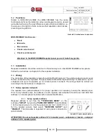
Page 69: ...xisting network panel is used for the connection of the repeaters The panel network should be implemented by 1 master panel up to 3 subpanels and up to 8 repeaters up to 12 total panels in network The...

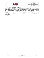
Page 70: ...is set to master panel from TECHNICIAN MENU on submenu SETUP by selecting PANEL NETWORK then select NETWORK SETUP and ENABLE and finally select PANELS DETECTION During panel detection master panel wi...

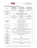
Page 71: ...siren circuits 4 x 24VDC 3VDC 300mA max short open circuit monitored 10k termination resistor 24VP Output 24VDC 3VDC permanent output 300mA max short circuit monitored 24VM Output 24VDC 3VDC resettabl...

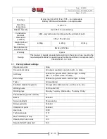
Page 72: ...for operating environment conditions in compliance with 3K5 EN 60721 3 3 1995 9 1 Factory default settings Registered points None Conventional sirens All outputs enabled on general alarm no delay AUX...

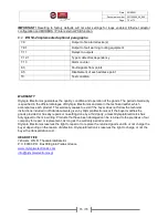
Page 73: ...in the technical leaflet which accompanies each product This warranty ceases to exist if the buyer does not follow the technical instructions included in official documents given by Olympia Electronic...

Reviews: