
Date 29/6/2021
Document number 921100409_09_002
Page 42 of 73
42 / 73
4.7
Other connections
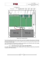
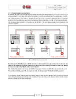
The following section contains information for other available connections in the control panel.
For each of the following connection a separate cable must be used
(don’t use multicore cables to
connect multiple outputs).
The cables’ shielding must be connected to “Protective Earth” ground
(it is recommended to use the
metallic ground bar terminals inside the panel – top side).
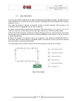
On the input / output board the following outputs are available:
-
24VM:
24V
DC
(300mΑ max) generic output used for power supplying gas detectors or other devices
of which the power supply must be interrupted via reset. Output is interrupted for 10” during reset.
-
24VP:
24V
DC
(300mΑ max) permanent generic output used for power supplying peripheral devices
(e.g. a door’s electromagnetic lock) that their input shall not be interrupted during reset.
-
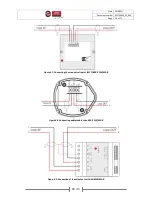
ALARM Relay
: Potential free relay contacts that are triggered during an alarm event (C-NO contact
circuit active when on alarm). 30V
DC
/3A max.
-
FAULT Relay
: Potential free relay contacts that are triggered during a fault event (C-NC contact
circuit active when on fault). 30V
DC
/3A max.
-
AUX
Relay
:
Potential
free
relay
contacts
with
a
programmable
output
(alarm/fault/prealarm/zone/task). With selectable initial state (positive/negative logic) and optional
delay. 30V
DC
/3A max.
-
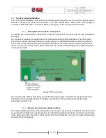
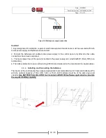
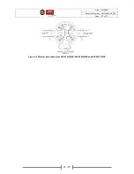
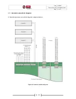
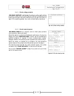
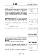
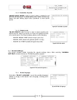
EXTRA Relays
:
On middle section of the input / output board there are located 2 connection
sockets for connecting extra relays (BS-613). Each connection socket controls 4 outputs and is
marked with the tag “
Extra Relays 1-4
” or “
Extra Relays 5-8
”. Each one of the 8 in total outputs is
programmable (alarm/fault/prealarm/zone/task), with selectable logic (positive/negative) and
optional delay. 30V
DC
/3A max.
Figure4-13.Extra relay connections (for BS-613)
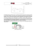
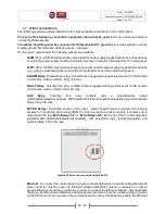
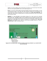
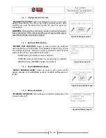
-
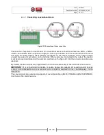
Ethernet
: To connect the control panel to a local network (Ethernet) a network cable with a RJ45
male connector must be used. An Ethernet adaptor (GR-8530) must be connected in order to
provide Ethernet connectivity (optional). In order to connect the Ethernet adaptor, first deactivate
the panel, by disconnected batteries and mains power and place it on the corresponding connector
on the CPU board. Then power on the control panel and connect the batteries, enable the Ethernet


