Date 29/6/2021
Document number 921100409_09_002
Page 36 of 73
36 / 73
4.4.1
Loop Connections
All models of the BSR-100X/MAR family, BSR-1001/MAR, BSR-1002/MAR and BSR-1004/MAR share the
same architecture, thus same loop connection method. They differ only on the available loop connection
outputs (1, 2 or 4).
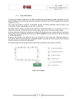
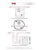
The output connections, maximum consumption and the connection diagrams that are going to be
mentioned in the next paragraphs are common to all panels.
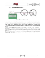
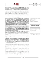
By default, all loop output connection terminals have 2 short-circuit links (+L to +LF and –L to –LF). In
order to connect one or more devices to the loop output, remove the 2 short-circuit links entirely.
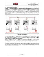
All loop connections are similar. A maximum number of 150 devices can be connected in each loop. Some
devices may require 2 addresses to function (e.g. BSR-8120/MAR), thus the maximum number of devices
is reduced respectively.
Moreover, the shields of all cables must be all connected to the vessel hull (“Protective Earth”) in
accordance with the electromagnetic compatibility (EMC) requirements. Use the ground bar terminals
inside the panel to connect the cable shields.
The cable length must not exceed the limit of 2km with a maximum cross section of 2,5mm².
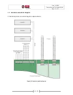
Figure 4-5.Loop diagram

