Date 29/6/2021
Document number 921100409_09_002
Page 43 of 73
43 / 73
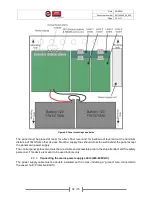
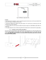
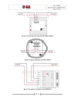
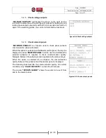
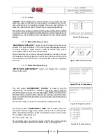
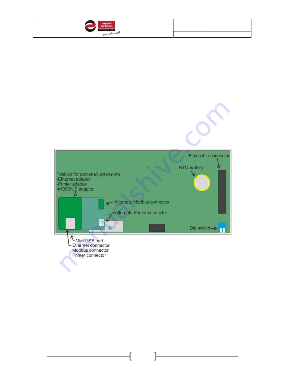
adaptor set up the IP address of the control panel via Technician menu and connect the network
cable to the corresponding RJ45 socket on the adaptor (figure 4-14).
-
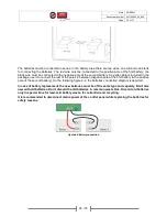
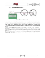
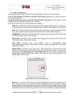
Printer
: To connect a printer adaptor, disconnect batteries and mains power and place it on the
corresponding connector on the CPU board (same position of figure 4-14). Then power on the
control panel and connect the batteries, go to Technician menu “
EXT. PCB FUNCTION
” and
enable printer option. While the thermal printer is connected and enabled, all new events recorded
will be printed on paper.
-
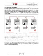
MODBUS
: To enable MODBUS communication between the control panel and a Building
Monitoring System, a MODBUS adaptor must be installed. Disconnect batteries and mains power
and place it on the corresponding connector on the CPU board (same position of figure 4-14). Then
power on the control panel and connect the batteries, go to Technician menu “
EXT. PCB
FUNCTION
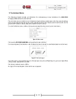
” and MODBUS option. Select the control panel’s MODBUS address via “SELECT
MODBUS ADDR.” option in Technician menu.
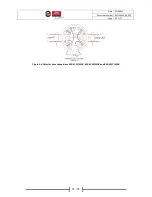
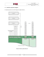
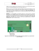
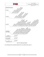
Figure4-14. Correct placement of Ethernet Adaptor, all the way to the left. (i.e., Use the first 10
pins from the left)


