Date 29/6/2021
Document number 921100409_09_002
Page 47 of 73
47 / 73
5.1.4
Device LED Address
“
DEVICE LED ADDRESS
” option starts a countdown procedure of 25
minutes while every connected fire detection device indicates its
address by a special flashing pattern that is repeating.
-
3burst short flash
-
2 seconds gap
-
number of flashes multiplied by tens (with 1s gap between)
-
5 seconds gap
-
2burst short flash =>2s gap
-
number of flashes multiplied by ones (with 1s gap between)
-
5 seconds gap
-
repeat
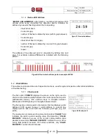
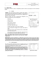
The address of the observed point is calculated by adding tens and
ones. For example, address #
124
will be indicated with the following
pattern:
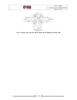
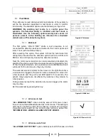
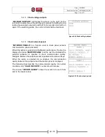
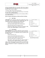
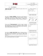
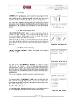
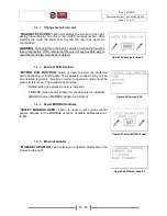
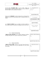
Figure5-7.Device led address
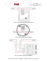
Figure5-8.Device led address pattern example of #124
5.2
Check Menu
This submenu is insisted of a set of inspection functions, used for system inspection, after initial installation
or troubleshooting.
5.2.1
Check points
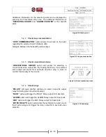
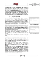
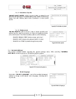
The first option “
POINTS
” displays the screen on the right, used to
check communication quality between the control panel and a point
(addressable device). Use up/down keys to navigate between
addresses and left/right keys to navigate between loops.
The first section contains point’s information, first line displays points
address (1.001 equals to loop 1, point address 1), second line
displays point’s name and third line indicates point type (e.g. call
point).
The next section contains point’s communication data. “
VALUE
” field
indicates the point’s current reading value (fire detection), “
VALID
PACKETS
” indicate the sum of the correct communication data
packets received and “
INVALID PACKETS
” indicate the sum of the
wrong data packets received. On normal conditions, only “
VALID
PACKETS
” counter should increase.
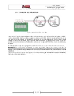
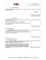
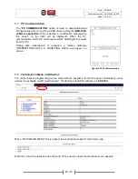
Figure5-9.Check point 1

