background image

Oki  Data  CONFIDENTIAL

44871001TH Rev.6 

3-11

3. MFP INSTALLATION

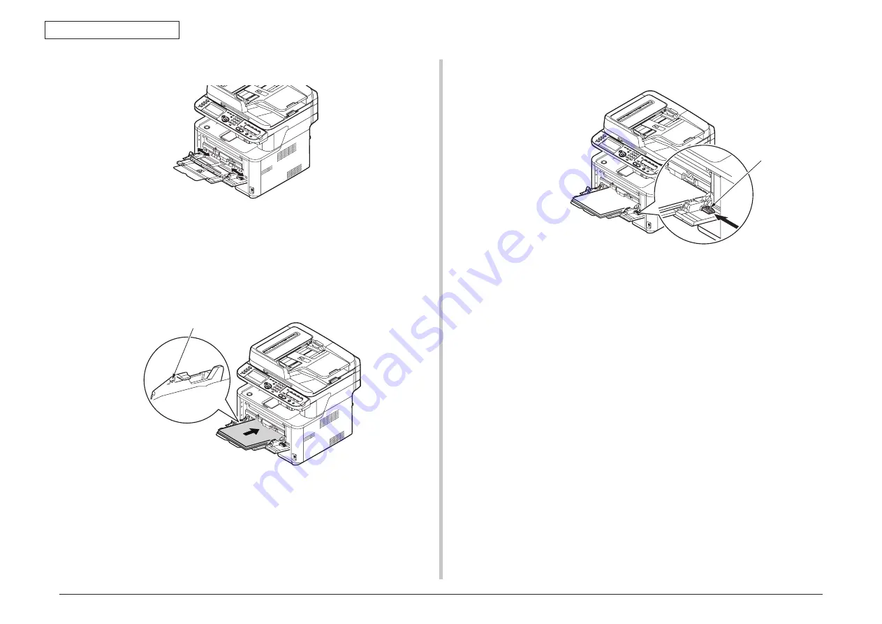
(4)  Adjust the manual feeding paper guide to the width of paper to be loaded.. 

(5)  Insert the paper with the print side face up until its edge touches the paper feed 

entrance.

Note!

  Do not load paper above the fill line.

(6)  Press the Set button.


Register the loaded paper on the machine.


Proceed to "Configuring the Tray Settings".

Note!


• 

Do not load paper of different sizes, types or weights at the same time.


  When  adding  paper,  remove  the  paper  on  the  MP  tray  and  straighten  the 

edges of both stacks of paper, and then load them again.


• 

Do not put anything other than paper for printing.

Memo!

 When  loading  envelopes  on  the  MP  tray,  load  them  face  up  with  the 

orientation as stated below.

-  You  envelopes  (Monarch,  Com-9,  Com-10,  DL  and  C5)  are  loaded  with 

the  flap  folded  and  the  flap  should  come  to  the  right  side  to  the  feeding 

direction.

Set button

Fill line

Summary of Contents for MB461MFP

Page 1: ...MB461 MB471 MB491 MB491 MB491 LP MPS4200mb MPS4700mb Maintenance Manual 031314C ...

Page 2: ... other manufacturers and referred to in this guide will not affect the applicability of the information in it Mention of software products manufactured by other companies does not necessarily constitute endorsement by the manufacturer While all reasonable efforts have been made to make this document as accurate and helpful as possible we make no warranty of any kind expressed or implied as to the ...

Page 3: ...rts have been made to make this document as accurate and helpful as possible we make no warranty of any kind expressed or implied as to the accuracy of the information contained herein Oki Data assumes no responsibility to the damages caused or claimed to have been caused by the user as a result of repair adjustment and or change using this manual Parts of this product are delicate and can be dama...

Page 4: ... USB Host Interface Signal 1 27 1 5 5 Wireless LAN Interface MB451w MB471w 1 28 1 5 5 1 Outline of Wireless LAN 1 28 2 OPERATIONAL EXPLANATION 2 1 2 1 Electrophotographic process mechanism 2 2 2 2 Printing process 2 6 2 3 Toner entrance detection 2 9 2 3 1 Toner sensor detection principle 2 9 2 3 2 Toner count principle 2 9 2 4 Image Scanning process 2 10 2 4 1 Structure and process of RADF 2 10 2...

Page 5: ...MB461 MB461 LP ES4161 MFP 4 24 4 2 8 13 LCD assy 4 25 4 2 8 14 Frame assy FB 4 26 4 2 8 15 How to remove Battery SU Board MHE 4 28 4 2 8 16 Frame assy hopping ADF 4 29 4 2 9 Plate Stay L Plate Assy Stay R 4 30 4 2 10 LED Head 4 31 4 2 11 Frame Assy TR 4 31 4 2 12 Duplex Belt Assy 4 32 4 2 13 DC Motor 4 32 4 2 14 Hopping Clutch MPT Clutch Regist Clutch 4 34 4 2 15 HV Board Motor FAN 4 37 4 2 16 Cov...

Page 6: ...Cleaning of LED lens array 7 2 7 1 4 Cleaning the Feed rollers and the Retard roller 7 3 7 2 Cleaning Rollers in the ADF 7 4 7 3 Cleaning the Document Glass 7 5 8 TROUBLESHOOTING PROCEDURES 8 1 8 1 Precautions prior to repair 8 2 8 2 Items to be checked prior to taking action on abnormal images 8 2 8 3 Precautions when taking action on abnormal images 8 2 8 4 Preparations for troubleshooting 8 2 8...

Page 7: ...2 3 1 Precautions on replacing parts 10 11 10 2 3 2 Arrangement of Parts 10 12 10 2 3 3 How to Replace Parts 10 13 10 2 4 Cleaning of Paper Feed Roller and Separation Roller 10 19 10 2 5 Procedure for Troubleshooting 10 20 10 2 5 1 Precautions for Troubleshooting 10 20 10 2 5 2 Preparation before Troubleshooting 10 20 10 2 6 Connection Diagram 10 21 10 2 6 1 Connection diagram 10 21 10 2 6 2 Board...

Page 8: ...Oki Data CONFIDENTIAL 1 CONFIGURATION 1 1 System configuration 1 2 1 2 Structure of MFP 1 3 1 3 Offer of Options 1 4 1 4 Specifications 1 5 1 5 Interface specifications 1 25 ...

Page 9: ...upter Photo Interrupter Black 2 Blue 2 Yellow 2 Blue 3 Black Black 2P Black Red Yellow Black White Black 2 3P AC Inlet Purple 3 Red 9 Black 2 White 8 White 2 White Black 2 8P Cover Open SW 28P CN1 TR CN2 High Voitage Board 97H 3P 3P 2 SB CN3 DB CH FUSECUT RETURN ID Unit TAG Toner Cartidge White Black White Black Red 3 Face up down SW 2P 3P 2P 3P 9P 4P 8P 2P FACE UP PW FAN1 HVIF 28P IL 2ND THERM DM...

Page 10: ... MFP The insides of multi function printers are composed of the following parts Scanner part Electronic photography process part Paper path Control part CU part PU part Power supply parts high voltage part low voltage part Figure 1 2 shows the composition of the MFP Figure 1 2 ...

Page 11: ...Oki Data CONFIDENTIAL 1 CONFIGURATION 44871001TH Rev 6 1 4 1 3 Offer of Options This product can be installed with the following option 1 Second Tray Unit ...

Page 12: ...ost Script3 PCL6 PCL6 PostScript3 Option N A Scanner Type Flat Bed RADF Resolution Max 600 x 600dpi Copy speed A4 1to1 High Speed 29cpm 33cpm 38cpm Operation Panel LCD 320 x 128dot Graphic panel w Back light QWERTY N A Image Drum for EDT model is included starter toner Category Item MB441 MB461 ES4161 MFP MB451 MB471 MB451w MB471w MB491 ES4191 MFP MPS4200mb Interface USB2 0 Ethernet Wireless LAN N...

Page 13: ...0 50 70 Print quality assurance humidity Maximum wet bulb temperature 25 C During non operation 10 90 Maximum wet bulb temperature 26 8 C power OFF During storage 10 90 Maximum wet bulb temperature 35 C During transportation 10 90 Maximum wet bulb temperature 40 C Others USB IF logo Yes Windows logo Yes Operations on UPS Operations on UPS uninterruptible power supply are not guaranteed Do not use ...

Page 14: ...600 x 600dpi Copy speed A4 1to1 High Speed 33cpm 38cpm Operation Panel LCD 320 x 128dot Graphic panel w Back light QWERTY N A Category Item MB461 LP MB491 MB491 LP MPS4700mb Interface USB2 0 Ethernet Wireless LAN N A Parallel N A Facsimile N A USB Memory SD Memory Card N A 4GBytes Except MB491 Dimensions mm W x D x H 427 x 425 x 455 Weight kg 20 Power con sumption Power input 110 127VAC Range 99 1...

Page 15: ... assurance humidity Maximum wet bulb temperature 25 C During non operation 10 90 Maximum wet bulb temperature 26 8 C power OFF During storage 10 90 Maximum wet bulb temperature 35 C During transportation 10 90 Maximum wet bulb temperature 40 C Others USB IF logo Yes Windows logo Yes Operations on UPS Operations on UPS uninterruptible power supply are not guaranteed Do not use UPS ...

Page 16: ...65Kg plain paper Paper size 1st 2nd tray A4 A5 A6 B5 Letter Legal 13 Legal 13 5 Legal 14 Executive 16K 184 x 260mm 16K 195 x 270mm 16K 197 x 273mm Statement Custom A6 and Custom cannot be used in tray 2 Category Item MB461 MB461 LP ES4161 MFP MB471 MB471w MB491 MB491 MB491 LP ES4191 MFP MPS4200mb MPS4700mb Paper size Multi purpose tray A4 A5 A6 B5 Letter Legal13 Legal13 5 Legal14 Executive Stateme...

Page 17: ...ment size Flat bed 4 13 x 5 8 8 5 x 11 69in 105 x 148 215 9 x 296 9mm for MB461 LP MB491 LP and MPS4700mb 4 13 x 5 8 8 5 x 14in 105 x 148 215 9 x 355 6mm RADF Simplex A6 Legal14 Duplex A5 Legle14 Document thickness Flat bed 20mm RADF Simplex Duplex 60g m2 105g m2 Reversing Auto document feeder sheets RADF 50 sheets 80 g m2 Maximum scanning range Flat bed Maximum 215 9 x 296 9mm for MB461 LP MB491 ...

Page 18: ... 141 A5 A4 Edge Erase Set ON OFF Erase Width 2 50mm increments of 1mm 0 1 2 0 inch increments of 0 1 inch Margin shift Front Left Top 0 25 mm 0 0 1 0 inch 1mm Step Back Left Top 0 25 mm 0 0 1 0 inch 1mm Step N up Document pages OFF 2 in 1 4 in 1 Vertical 4 in 1 Horizontal ID Card Copy ID Card Copy OFF ON Repeat Copy OFF 2 times 4 times Poster Copy N A Document Direction Portrait Landscape Categori...

Page 19: ...ackground Removal OFF 1 2 3 4 5 6 Blocks out the color background of the image assuming document has a color background so that the background color would not be printed Density 3 2 1 0 1 2 3 Adjusts the darkness of images Resolution Color 75 100 150 200 300 400 600dpi 400 600 can be set only for FB The resolution in which a document is scanned is selected 1 Mono Grayscale 75 100 150 200 300 400 6...

Page 20: ... password to open created PDF documents Setting from Admin Setting Either Password to open a document or Access password must be set Not set may not be selected for both Items Setting Description Set Password Re enter Password Default value is NULL Sets a password to open created PDF document NULL by default Characters that can be entered are 1 to 32 alphanumeric characters Upper Lower case letter...

Page 21: ...uplex Scan is not supported for A6 document Items Setting Address confirmation To Cc Bcc Up to 256 entries Address Book List of Email addresses added to the Address Book Up to 100 Address Book Group Group number Up to 20 Mail Send History Email addresses manually typed in Up to 50 LDAP E mail Address from LDAP Server Up to 100 entries can be displayed after search Send destination Direct Input An ...

Page 22: ... document is first scanned from ADF and then if there is none in ADF from FBS assuming there is in Flatbed Color 24bit Grayscale 8bit B W Halftone No halftone scanner output Executed on Scanner Driver side Scan Mode Resolution 75 100 150 200 300 400 600 800 1200 2400 4800dpi Scanner s basic performance varies with the selection of Color mode among other settings and if a resolution exceeding this ...

Page 23: ...ings and if a resolution exceeding this basic performance is specified the driver runs the resolution process Scan Size Custom ADF Min 105 x 148 mm Max 215 9 x 355 6 mm Flatbed Min 105 x 148 mm Max 215 9 x 296 9 mm for MB461 LP and MB491 LP and MPS4700mb Flatbed Min 105 x 148 mm Max 215 9 x 355 6 mm Preset A4 A5 B5 A6 Legal13 Legal13 5 Legal14 Letter Executive A6 Duplex Scan not supported Image Pr...

Page 24: ...Legal 14 in addition to above sizes Scanning mode Normal 8 dots 3 85 lines mm 203x98dpi Fine 8 dots 7 7 lines mm 203x196dpi Ext Fine 8 dots 15 4 lines mm 203x391dpi Photo 8 dots 7 7 lines mm 203x196dpi Density adjustment 3 2 1 0 1 2 3 Duplex scanning Support Job Build Support Function Description Tx function Send Transmission Real time Tx Support Memory Tx Support Manual Tx Support Dial Direct dia...

Page 25: ...ctive record size Legal14 Legal13 5 Legal13 Letter A4 Print margin same as printer Threshold level The value that determines the position in which received images are clipped or reduced when they do not fit in valid recording paper sizes Page split If the portion exceeding the valid recording size is larger than the threshold the page is split Reduction Auto or 100 Duplex print Support Printer s D...

Page 26: ...gement Report Reports Receive records a summary of information At reception of MDN reply Communication report A report printed automatically at reception of MDN reply At reception of DNS reply Transmission confirmation report A report printed automatically at reception of DSN reply Auto Transmission Data Save Auto IFAX Receive Auto delivery associated with IFAX Receive Communication Data Detention...

Page 27: ...Yes No No No No 15 Speed Dial List Yes No No No No 16 Group List Yes No No No No 17 Transmit Journal Receipt Journal Yes No No No Yes 18 Transmit Confirmation Report No No No No Yes 19 Check Message No No No No Yes 20 F CODE Box Journal No No No No Yes 21 Erased Report No No No No Yes 22 F Code Box List Yes No No No No 23 Block Junk Fax List Yes No No No No 24 T30 Monitor Yes No No Yes No 25 E mai...

Page 28: ...print One file at a time selected from the panel Print Range The entire file pages cannot be specified Print Mode Paper Size By the current Menu settings Size of paper presently loaded in the tray can be selected from the panel Copies By the current Menu settings With PRN by the value specified at a time of file creation Duplex Print By the current Menu settings With PRN by the value specified at ...

Page 29: ...on pdf jpg jpeg tif tiff Printing sequence Files are printed in the order in which they are attached Maximum number of attached files 10 File size limit Maximum size is 8MB per file Print Mode Paper Size By image s page size Copies By the current Menu settings Duplex By the current Menu settings Fitting Dependent on the file format N up No Others N A Print Range Entire file Cannot be specified by ...

Page 30: ... if the attached file format is PDF JPEG and TIFF if TIFF 4 Up to 16MB This depends on the available space on FAX memory at reception time Transmission Data Save Function for MB491 MB491 MB491 LP ES4191 MFP MPS4200mb MPS4700mb Items SD Card has to be installed Transmission Data Save input method From Product Web Page 1 Subject to Transmission Data Save FAX sent FAX received Email sent Email receiv...

Page 31: ...ed Use disabled PIN ID 1 10 digits Number of ID that can be registered Max 100 Register Edit Configuration Tool Web Page JA Server User Password 1 32 characters Number of ID that can be registered Max 100 Register Edit Configuration Tool User Authentication Method Local LDAP Secure Protocol Access Control and Job Accounting Functions Overview Specs Item Description Job Accounting Yes Number of JA ...

Page 32: ...1 5 1 2 USB Interface Connector and Cable 1 Connector Printer side B receptacle Upstream port Equivalent of UBR24 4K5C00 made by ACON 2 Cable Cable length Specification Cable of USB2 0 spec of less than 5m less than 2m is recommended 1 5 1 3 USB Interface Signal Name of Single Function 1 Vbus Power Supply 5V red 2 D Data transmission white 3 D Data transmission green 4 GND Single ground black Shel...

Page 33: ...P HTTP 1 5 2 2 Network Interface Connector and Cable 1 Connector 100 BASE TX 10 BASE T automatic switch no simultaneous use 1 8 1 5 2 3 Network Interface Signal Pin No Singles Single Direction Functions 1 TXD FROM PRINTER Send Data 2 TXD FROM PRINTER Send Data 3 RXD TO PRINTER Received Data 4 Unassigned 5 Unassigned 6 RXD TO PRINTER Received Data 7 Unassigned 8 Unassigned Connector pin arrangement...

Page 34: ...lephone Line Interface signal Contact No Functions TEL 1 Unspecified 2 Unspecified 3 TCP 4 TCP 5 Unspecified 6 Unspecified LINE 1 Unspecified 2 Unspecified 3 TCP 4 TCP 5 Unspecified 6 Unspecified TCP Terminal Connection Point 1 5 4 USB Host Interface 1 5 4 1 Outline of USB Host Interface 1 Basic Specification USB 2 Transmission Mode Hi Speed 480Mbps 0 05 max 3 Supply Power Max 500mA 4 Connection d...

Page 35: ...tline of Wireless LAN 1 Specification IEEE 802 11b g n 2 4GHz 2 Power connector USB Micro B 3 Power supply voltage 5V 4 MFP side interfaces IEEE 802 3u 10 100BASE LAN port USB Micro B Chip Antena LAN Port X Do not connect Blue Yellow Note This product cannot connect to a wired LAN and wireless LAN at the same time ...

Page 36: ...Oki Data CONFIDENTIAL 2 OPERATIONAL EXPLANATION 2 1 Electrophotographic process mechanism 2 2 2 2 Printing process 2 6 2 3 Toner entrance detection 2 9 2 4 Image Scanning process 2 10 ...

Page 37: ...fer roller 5 Fusing The toner image that is transferred to paper is fused on paper by heat and pressure 6 Drum cleaning The cleaning blade scrapes off the toner that was not transferred and remains on the image drum 7 Static elimination Residual potential on the image drum is removed 2 1 Electrophotographic process mechanism 1 Charging Charge the image drum surface by implying voltage to the charg...

Page 38: ...image developing roller is dropped down to the developing plate to make a thin toner film on the image developing roller side 3 The toner is attracted by the exposed part Low electrical potential part of the image drum when the image drum contact the image developing roller so as to see the electrostatic latent image Note The necessary bypass voltage in image processing is impressed on the toner f...

Page 39: ...is transferred to the surface of feeding paper by the plus charge of the backside of the paper 5 Fusing After the termination of transfer the unsettled toner image is settled to paper by heat and pressure while passing between Heat roller and Back up roller Heat roller is Teflon coated and is mounted by heater that can generate heat Halogen lamp The thermistor that contacts the Heat roller adjusts...

Page 40: ...moving light 6 Drum cleaning After completion of transfer the toner remaining on the image drum is scraped off by the cleaning blade As a result of this the surface of the image drum is cleaned and the remaining toner that has been scraped off is collected as waste toner in a waste toner area 7 Static elimination After completing transfer the image drum is illuminated with its surface to decay sta...

Page 41: ...oller and resist roller When feeding paper is from MPT it is conveyed by MPT feeding roller and resist roller After that the feeding paper that is conveyed by image drum and the nip part of transfer roller forms toner image on the paper through electrophotographic process And then the toner on the paper is fused by the heat and pressure as the fuser unit passing through The paper that fused the to...

Page 42: ...n clutch Registration roller Paper Entrance sensor lever Writing out sensor lever MPT paper feeding roller 2 Paper feeding from Multipurpose tray MPT MB451 MB451w MB471 MB471w MB491 MB491 MB491 LP ES4191 MFP MPS4200mb MPS4700mb 1 As DC motor rotating Clockwise rotation if set paper feeding clutch as ON the MPT paper feeding roller starts to rotate the paper in the tray is conveyed 2 After setting ...

Page 43: ...istration clutch Registration roller Entrance sensor lever Eject motor Counterclockwise rotation Fuser unit Eject roller Eject roller Heat roller Ejecting sensor lever Separator Belt Duplex conveying roller Duplex conveying roller Writing out sensor lever DC motor Clockwise rotation Duplex conveying roller Duplex conveying roller Registration clutch Registration roller Entrance sensor lever Writin...

Page 44: ...r sensor are facing each other at an improper position due to improper setting of the ID unit or any reasons toner low cannot be detected correctly and a toner sensor error occurs Light board Toner sensor 2 3 2 Toner count principle After the image data is transformed into binary data which can be printed by the printer the data is counted as print dot number by LSI The amount of the used toner is...

Page 45: ...ion pad Lower pinch roller Transfer roller Paper stocker Pinch roller 2 4 1 2 Electrical configuration Electrical circuit configuration This Scanner is controlled by the SU board MHE The ASIC mounted on the SU board MHE control the DC load devices such as motor solenoid and clutch via the ADF board MHD in dependance of the sensor signals and control signals from the CU PU board 98M not to be shown...

Page 46: ...e instructions given by the connected equipment to implement the print operation Name of the operation modes the overview of the operation and the corresponding print modes are shown in the following table Name of the operation modes Overview of the operation Supporting print modes 1 Normal direction feed paper Unload paper Document is fed and scanned Upon completion of scan document is unloaded a...

Page 47: ... sided document single sided print operation Outline of document flow is shown below Supplement When a single sided document is selected this operation is performed regardless of the same size mixed documents or different sizes mixed documents Feeding paper Scanning Loop creation Discharging paper Job end Scaning stand by ...

Page 48: ...ne of document flow is shown below Supplement When a both sided document is selected this operation is performed regardless of the same size mixed documents or different sizes mixed documents Inversion Transport Scaning stand by Transport Feeding paper Loop creation Inversion Scanning Transport Transport Scaning stand by Transport Discharging paper Scanning Loop creation Job end ...

Page 49: ...on signal SET telling that a document is set to the connected equipment via the ADF board MHD Detection of final document The document set sensor PI14 detect if the document that has started of the final document has passed the set sensor lever the detection lever moves together with the light shielding plate so that the photo interrupter that has been shutting down the light passes the light Thus...

Page 50: ...n be judged from the information if a document exits or not at the corresponding sensor block PI11 PI12 PI13 PI14 PI11 Regist paper sensor PI12 Reverse paper sensor PI13 Cover open close sensor PI14 Document set sensor 2 4 2 Document table structure 2 4 2 1 Overview Flatbed unit consist of Cover Top Assy Frame Bottom Assy Carriage Assy and Flatbed drive block The lamp LED is located on top of the ...

Page 51: ...rms the function of irradiating the lamp light uniformly over a document while moving its position The carriage Assy is driven by a belt which is driven by the FB motor Scanner moves at the scan speed corresponding to the respective magnification ratios that are set with reference to the standard scanning speed Home position of the carriage Assy is the position where the home sensor is located The...

Page 52: ...on 3 2 3 2 MFP Unpacking Procedure 3 3 3 3 MFP Installation Instructions 3 4 3 4 Packed Units and Attachments 3 5 3 5 Assembly Procedure 3 6 3 6 Configuration Page Print 3 20 3 7 Network Information Print 3 22 3 8 Connection Procedures 3 23 3 9 Checking of User Paper 3 27 ...

Page 53: ...ridge or image drum cartridge into fire Burn may occur by the dust explosion Do not use a highly flammable spray near the MFP Fire may break out as there are high temperature parts inside the printer When the cover becomes abnormally hot a smoke arises or a strange odor comes out remove the power plug from the outlet and contact the Customers Service Center Fire may break out When liquid like wate...

Page 54: ... MFP INSTALLATION 3 2 MFP Unpacking Procedure Warning Personal injury may occur This MFP weighs about 20kg So lift it up with 2 or more persons Open the upper lid Take out the accessory box Remove the upper buffer material Take out the equipment ...

Page 55: ... Wet Bulb Temperature 25 C Be careful not to be bedewed When the MFP is to be installed at a place where the humidity is less than 30 use a humidifier or a static electricity prevention mat Installation Space Place the MFP on a flat desk with enough space for the legs of the MFP Secure enough space around the MFP Top View Side View 50cm 96cm Side View tray 2 installed 50cm 110cm 20cm 193cm 20cm 50...

Page 56: ... the user s section in charge and follow its instruction Warning Personal injury may occur This MFP weighs about 20kg and should be lifted by 2 or more persons MFP main body Image Drum Cartridges with Starter Toner Cartridges installed in the MFP Explain to customers that the toner cartridge and the image drum cartridge are separable MFP Software DVD Power Cord Warranty and Registration Card Set u...

Page 57: ...where it is to be installed Note Do not open the scanner unit till the procedure no 9 is completed 2 Remove the protection tapes at the top and sides of the machine to take out cushioning materials 3 Remove the protection tapes to open the MP tray 4 Remove the protection tape to pull the paper up Cushioning materials Protective tape Protective tape Protective tape ...

Page 58: ...move the protection tapes Open the ADF and remove packaging tapes 8 Close the document glass cover Now you can open or close the scanner 9 Open the scanner unit 10 Remove the protection tapes and remove desiccants and films 11 Press the top cover open button and open the top cover Protective tape Top cover open button ...

Page 59: ... image drum in the printer lower it into place in the printer locating the pegs at each end into their slots in the sides of the printer cavity 15 Turn the lever in the direction shown The arrow on the lever should align with the arrow on the image drum When the toner cartridge is not fully fixed a decline in print quality may occur 16 Close the top cover 17 Close the scanner unit Reference Please...

Page 60: ...onal Memo The following procedure uses tray 1 as an example but the same is applied to tray 2 1 Pull out the paper tray 2 Slide the paper guide 1 to the width of paper to be loaded 3 Slide the paper stopper 2 to the length of paper to be loaded Paper guide Paper stopper 4 Flex paper back and forth and then fan it Straighten the edges of the paper stack on a level surface ...

Page 61: ...h the paper tray until it stops Register the loaded paper on the machine Proceed to Configuring the Tray Settings P 3 22 Loading Paper on the MP Tray MB451 MB451w MB471 MB471w MB491 MB491 MB491 LP ES4191 MFP MPS4200mb MPS4700mb The following procedure explains how to load paper on the MP tray 2 Pull out the paper support 3 Pull out the sub support 1 Open the MP tray ...

Page 62: ... to Configuring the Tray Settings Note Do not load paper of different sizes types or weights at the same time When adding paper remove the paper on the MP tray and straighten the edges of both stacks of paper and then load them again Do not put anything other than paper for printing Memo When loading envelopes on the MP tray load them face up with the orientation as stated below You envelopes Mona...

Page 63: ... Manual Feeder MB441 MB461 MB461 LP The following procedure explains how to load paper on the Manual Feeder 1 Open the Manual Feeder 2 Adjust the manual feeding paper guide to the width of paper to be loaded 3 Load a paper Note Only one sheet can be set in the Manual Feeder each time ...

Page 64: ...uments Loading Documents on the Document Glass 1 Lift and open the document glass cover 2 Place a document face down on the document glass If your document is portrait align its top edge to the upper left corner of the glass If your document is landscape align its right edge to the upper left corner of the glass 3 Close the document glass cover gently Reference If you want to use N in 1 Sort or Du...

Page 65: ...not use the damaged electric cord Do not put many loads on one electric outlet Do not connect this MFP to the same outlet with other electric machines Particularly erroneous operation may occur by electric noise when the same outlet is shared by the air conditioner duplicator shredder etc at the same time When the same outlet had to be used use a noise filter or noise cut transformer on the market...

Page 66: ... and power switch indicator blinks every 1 second Then the machine turns off automatically and power switch indicator goes out Note Turn the power off and when turning the power back on again push the power switch after waiting for a few seconds Reference The machine has the power save mode and sleep mode and the auto power off function For details on them refer to the User s Manual Basic 1 Setup ...

Page 67: ...stalling a Second Tray Unit IInstall an optional second tray unit tray 2 when you want to increase the paper capacity of the machine After installation you need to configure the printer driver settings Reference For the specification of the second tray unit Tray2 refer to Loading Paper P 3 9 Model Number N22204A Installation Warning At least two people are needed to lift the MFP safely 1 Hold down...

Page 68: ...Oki Data CONFIDENTIAL 44871001TH Rev 6 3 17 3 MFP INSTALLATION 4 Attach the lock parts 5 Plug the AC cable and Ethernet or USB cable into the machine and then push the power switch ...

Page 69: ...lick Start Control Panel Printer For Windows XP Windows Server 2003 click Start Printers and Faxes 2 Right click the OKI MB491 icon and select Printer properties For Windows Server 2008 Windows Vista Windows Server 2003 and Windows XP select Properties For Windows 7 if you have installed multiple printer drivers select Printer properties OKI MB491 PCL or OKI MB491 PCL XPS 3 Select the Device Optio...

Page 70: ...ct System Preferences from the Apple menu 2 Click Print Scan 3 Select the name of the machine and then click Options Supplies 4 Select the Driver tab 5 Select the total number of trays installed on the machine for Available Tray and then click OK For Mac OS X PS PCL Driver Mac OS X 10 4 Note This procedure uses Mac OS X 10 4 as an example This procedure uses MB471 driver as an example 1 From Go se...

Page 71: ...TH Rev 6 3 20 3 6 Configuration Page Print Make sure that the MFP operates normally 1 From the panel press Setting button 2 Select Reports 3 Select Configuration Press the down button to go to Configuration and then press the right button Sample MB461 ...

Page 72: ...Oki Data CONFIDENTIAL 44871001TH Rev 6 3 21 3 MFP INSTALLATION Sample MB471 Sample MB491 ...

Page 73: ...twork Information Print Make sure that the MFP operates normally 1 From the panel press Setting button 2 Select Reports 3 Select System 4 Select Network Information Press the down button to go to Network Information and then press the right button Sample In case of MB491 ...

Page 74: ...USB interface connector Switch off the power of the MFP and computer Memo Although the USB cable can be connected or removed with the switch of the computer and printer on switch off the power of the MFP at this step in order to ensure installation of the MFP driver and USB driver later Important For Windows OSs do not plug the other end of the USB cable into the computer until prompted while driv...

Page 75: ...N LAN Cable Connection Prepare the LAN cable Switch off the power of the MFP and computer Connect the computer and MFP 1 Plug one end of the Ethernet cable into the network connection on the back of the MFP 2 Plug the other end of the Ethernet cable into the hub ...

Page 76: ... end into a Public Line Analog Note Connect telephone cable to LINE connection without fail Never connect it to TEL connection Connecting for Fax and Telephone 1 Plug one end of the Telephone cable into the LINE connection of the machine and the other end into a Public Line Analog 2 Remove the Telephone connector cover LINE connection Telephone cable Public Line Analog LINE connection Telephone ca...

Page 77: ...ed to the machine is only one Don t connect the telephone to the machine in parallel If you connect the telephone to the machine in parallel the following problem will occur and the machine will not work correctly TEL connection When you send fax or receive the fax picture may be broken or communication error may occur by picking up the telephone The fax transfer function is not able to work from ...

Page 78: ...M HEAVY Medium Heavy 90 105kg 105 122g m2 HEAVY Heavy 106 140kg 123 163g m2 ULTRA HEAVY Ultra Heavy Postcard 4 Envelope 4 Label 0 1 to under 0 15 mm HEAVY LABELS Label 1 1 The factory default for the media type is PLAIN 2 Media weight and type can be set on the operator panel and in the printer driver The settings in the printer driver take priority Data is printed out in accordance with the setti...

Page 79: ...The procedures are to detach them Reverse the procedures to attach them The reference part numbers used in this manual such as and do not identical to the part numbers in the maintenance disassembly configuration diagram 44871001TL and RSPL 44871001TR for the manual 4 1 Notes on replacement of parts 4 2 4 2 Part replacement procedure 4 4 ...

Page 80: ...ld be tentatively installed in their original positions 7 Do not use static prone gloves when handling integrated circuits ICs including microprocessors and ROM and RAM chips or circuit boards 8 Do not place printed circuit boards PCBs directly on the printer or a floor Unplugging Plugging b Always use the following procedure to reconnect the printer Connect the AC cord and the interface cable to ...

Page 81: ...0 1 3 Screwdriver No 5 200 1 4 Digital multimeter 1 5 Pliers 1 6 Handy vacuum cleaner toner vacuum 1 See note 7 E ring pliers 1 E shaped ring removal Note Use a toner vacuum Using a general purpose vacuum may cause fire Table 4 1 2 shows the tools necessary to use Maintenance Utility software Table 4 1 2 Maintenance Tools No Maintenance Tool Quantity Use Remarks 1 Notebook personal computer with M...

Page 82: ...blies shown in the disassembly diagrams below 4 2 1 Cover Side L 1 Remove the cassette assembly 2 Open the Scanner Cover Assy Stacker Frame Assy MPT and Cover Assy Rear 3 Unlatch the claws 10 portions with to pull the front side of the mainbody to the arrow in figure to detach the Cover Side L Cover Assy Stacker Caver Assy Rear Frame Assy MPT Scanner Points of craws ...

Page 83: ...e Cover Assy Rear 5 Remove the Screw Black and the Screw Silver 6 Unlatch the claws 7points with to pull the front side of the mainbody to the arrow in figure to detach the Cover Side R ACC LAN ACC LAN View A Caver Assy Stacker Caver Assy Rear Frame Assy MPT Scanner ViewA Points of craws Sponge paste position 21mm Upper Position next to the lower end of the rib Note If the new Cover Side R is repl...

Page 84: ...move four Screws Silver to detach the Board 98M LAN ACC View A View A View B View B Note If replaced new board update Firmware according to Chapter 9 3 It is necessary to take the synchronization of the firmware version of SU board and CU board For MB451 MB451w If Error 049 is displayed on LCD after replacing to the new Board 98M it is necessary to update the firmware according to Chapter 9 3 5 ...

Page 85: ... to touch the conductors or terminals of the power supply directly After the AC cord is unplugged the capacitor may take about one minute to discharge completely or due to PCB breakdown could not discharge Use caution about electric shock 1 Remove the Cover Side R Refer to 4 2 2 2 Disconnect cables from the PWR unit ACDC Switch 3 Remove two Screws Silver 4 Unlatch the claws 3 points to detach the ...

Page 86: ...44871001TH Rev 6 4 8 Oki Data CONFIDENTIAL 4 REPLACEMENT OF PARTS Note on removing installing 1 Assemble the POWER to main body in accordance to the groove on guides 2 points guide ...

Page 87: ...a CONFIDENTIAL 4 REPLACEMENT OF PARTS 4 2 5 Cover Stay R Cover Stay L 1 Remove the Cover Side L Refer to 4 2 1 2 Remove the Cover Stay L 3 Remove the Cover Side R Refer to 4 2 2 4 Remove the Screw Black to detach the Cover Stay R ...

Page 88: ...001TH Rev 6 4 10 Oki Data CONFIDENTIAL 4 REPLACEMENT OF PARTS 4 2 6 Cover Front Top 1 Remove the Cover Side R and Cover Side L Refer to 4 2 1 and 4 2 2 2 Remove two Screws Black to detach the Cover Front Top ...

Page 89: ...11 Oki Data CONFIDENTIAL 4 REPLACEMENT OF PARTS 4 2 7 SW Assy 1 Remove the Cover Side R Refer to 4 2 2 2 Close the Frame Assy MPT 3 Remove the Cable 4 Remove the Screw Silver and to detach the SW Assy View A Cable View A ...

Page 90: ...the Cover Stay R and Cover Stay L Refer to 4 2 5 3 Remove the Screw Silver and remove the FG Cable from Guide Cable 4 Remove the Screw Silver and remove Plate Shield CU 5 Disconnect the FFC and the Cable from the CU PU Board 6 Remove the Screw Silver and the Screw Black and remove the FG Film FFC and the Cable from the Guide Cable LAN ACC View A View A View B View B ...

Page 91: ...ing RE4 SK and screw 8 Remove the E shaped retainer ring RE6 SK 9 Remove the shaft stopper hinge and remove the shaft guide hinge 10 Remove the scanner Note to assemble 1 The case of to assemble for the scanner unit to the Mainbody insert the the Shaft Stopper hinge to the hole with the marked N on the Plate Assy Stay R ...

Page 92: ...e cover assy top ADF 2 Remove the tray assy document by pull it in the direction of the arrow 3 Open the ADF unit while pushing the portion B and push the claw of cover ADF R assy 4 Push the portion A Concurrent to push the 3 5 Remove the cover ADF R assy in the direction of the arrow Claw A Cover assy top ADF B B ViewA ...

Page 93: ... 4 2 8 1 2 Detach a connector and from the ADF board MHD and remove the screw to remove the FG cable FG cable Clamp cable 3 Remove the clamp cable and pull the cables out of the hinge and Open the ADF unit 4 Remove the ADF unit by insert the screwdriver to gap between ADF unit and flatbed unit Flatbed unit Screwdriver ...

Page 94: ... Open the ADF unit 2 Remove the sheet document 3 Remove two claws to remove the paper weight assy and two spring PW ADF Claw Claw ADF unit 0 5mm 0 5mm Attention of affix the sheet document 1 Degrease the affix area of ADF unit 2 Remove the peeling off sheet 3 Set the sheet document see the figure below 4 Close the ADF unit ...

Page 95: ...ARTS 4 2 8 4 Hinge assy L Hinge assy R 1 Remove two screws L 10mm and remove the hinge Assy R for MB461 LP MB491 LP MPS4700mb Remove two pairs of screw and washer L 10mm for MB461 LP MB491 LP MPS4700mb 2 Remove two screws L 10mm and remove the hinge Assy L L 10mm ...

Page 96: ...2 8 5 Cover ADF F Guide assy exit sub ADF assy ADF board MHD 1 Turn the ADF unit upside down and remove the support sponge 2 Remove the guide assy exit sub by pull it in the direction of the arrow 3 Open the cover top ADF 4 Push the claw of cover ADF F Cover top ADF Claw ...

Page 97: ...AL 4 REPLACEMENT OF PARTS 7 Remove the screw silver and remove the ADF board MHD 8 Remove two screws black and remove the ADF assy 5 Push the portion A 2 places Concurrent to push the 4 A 6 Remove the cover ADF F in the direction of the arrow ...

Page 98: ... Remove the guide assy C 6 Remove the guide assy D 7 Remove the E type retaining ring and remove the clutch 8 Remove the plate FG S 9 Remove the E type retaining ring and remove the clutch 10 Remove four screws black and remove the plate motor ADF 11 Remove two screws silver and remove the Motor KTL40M 12 Remove the bearing shaft and remove the roller assy eject ADF 13 Remove the retainer 4 spring...

Page 99: ... assy separator Spring separator Rubber friction 1 Remove the guide A sub with rubber friction 2 Remove the frame assy separator and spring separator Note If change the Remove the then degrease the and affix the If change the Remove the and together 4 2 8 8 Cable ADF Rev SNS 1 Remove the cable ...

Page 100: ...1TH Rev 6 4 22 Oki Data CONFIDENTIAL 4 REPLACEMENT OF PARTS 4 2 8 9 Cable ADF Reg SNS 1 Remove the cable 4 2 8 10 Frame assy OP 1 Remove eight claws to remove the frame assy OP View A View A Claws Claws Claws ...

Page 101: ...e the LCD cable while part A is raised in the direction of arrow 8 claws ViewA ViewA 8 Latches 3 Remove the rubber pad R and rubber pad L 4 Remove the button and lens to 5 Remove the cover bottom and cover cable and LCD assy 6 Remove eight latehes to remove the cover op panel 7 Remove the cover KB assy 8 Remove the film one touch and sheet one touch Method of removing LCD cable Part A LCD cable ...

Page 102: ... remove the OPE board OPM 2 Remove the LCD cable while part A is raised in the direction of arrow ViewA ViewA 8 claws 11 Latches Method of removing LCD cable 3 Remove the rubber pad R and rubber pad L 4 Remove the button and lens to 5 Remove the cover bottom and cover cable and LCD assy 6 Remove eleven latehes to remove the cover op panel Part A LCD cable ...

Page 103: ...44871001TH Rev 6 4 25 Oki Data CONFIDENTIAL 4 REPLACEMENT OF PARTS 4 2 8 13 LCD assy 1 Remove the LCD assy ...

Page 104: ...aulking 12 Remove seven screws black colored L 10mm M4 to remove the Cam hinge Note to assemble 1 Since a cable will be pushed by Plate Shield SU please place downward 4 2 8 14 Frame assy FB Note It exchanges it detaching the scanner unit from the MFP when the SU board is exchanged If replaced new board update Firmware according to Chapter 9 3 It is necessary to take the synchronization of the fir...

Page 105: ...44871001TH Rev 6 4 27 Oki Data CONFIDENTIAL 4 REPLACEMENT OF PARTS To printer To printer To printer A A B B C C D D L 10mm L 10mm L 10mm L 10mm L 10mm Only MB461 LP MB491 LP MPS4700mb ...

Page 106: ...he position of the battery is shown in the below picture 2 How to remove the battery Insert finger a needle or a rod in the gap between the battery and the its holder Rod Battery Battery Stopper Battery SU Board MHE Raise the battery up so that it is put on the battery stopper and remove it Battery Battery Stopper ...

Page 107: ... Oki Data CONFIDENTIAL 4 REPLACEMENT OF PARTS 4 2 8 16 Frame assy hopping ADF 1 Slide the Gear shaft hopping while opening the stopper Cear shaft hopping Stopper 2 Remove the Frame assy hopping ADF and the Stopper Assy Gate ...

Page 108: ...y Stay R 1 Remove the Scanner unit Refer to 4 2 8 2 Remove three screws and remove the plate support L Remove three screws and remove plate stay L 3 Remove the Cover Front TOP Refer to 4 2 6 4 Remove the Plate Bracket CU Refer to 4 2 14 5 Remove four screws Silver to detach the Plate Assy Stay R ...

Page 109: ...dure with removing Note Beware of not to touch or press the SLA parts of LED Head directly 4 2 11 Frame Assy TR 1 Open the Stacker Cover 2 Remove the ID UNIT 3 Take the Frame Assy TR out of the printer 4 Disengage the latches of Bearing TR on both ends 5 Hold the Bearing TR on the both side and then lift up the Roller Transfer At this moment Gear TR is also removed 6 Installing is performed by the...

Page 110: ... Clutch in the direction of the arrow 4 Remove the screw Silver and Frame Duplex Assy 5 Remove the four pieces of Bearing Roller Feed Duplex and Duplex Belt 6 Installing is performed by the inverse procedure with removing Shaft Dup Clutch 4 2 13 DC Motor 1 Remove the Cover Side R Refer to 4 2 2 2 Remove the screw Silver and remove FG Cable 3 Remove four screws Silver and remove PlateShield CU LAN ...

Page 111: ...ove the PWR unit ACDC Switch Refer to 4 2 4 6 Unlatch the claws 2points and remove the Motor FAN 60 x 25 from the Duct Fan Power Air Claw 7 Remove three screws Silver to detach Duct Fan Power 8 Remove three screws Silver to detach DC Motor Note to assemble 1 Note to assemble for the direction of the Motor FAN s air flow ...

Page 112: ...and remove FG Cable from the Guide Cable 3 Remove the screw Black and the screw Silver and remove FG_Film FFC and Cable from Guide Cable 4 Remove the Guide Cable Push 5 Remove the PWR unit ACDC Switch Refer to 4 2 4 6 Remove the DC Motor Rever to Refer to 4 2 13 7 Remove nine screws silver to detach the Plate Bracket CU Clamp together the screw and the FG Film Note to assemble ...

Page 113: ...s Silver remove the Plate Gear 12 Remove the Gear Reduction 13 Remove the E ring RE3 SK remove the Regist Clutch 14 Remove the E ring RE3 SK remove the Hopping Clutch Remove the Spring from the current Regist Clutch or the current Hopping Clutch This Spring can be used to the new Regist Clutch or the new Hopping Clutch 15 Remove the MPT Clutch and the Gear MPT MB451 MB451w MB471 MB471w MB491 MB491...

Page 114: ...44871001TH Rev 6 4 36 Oki Data CONFIDENTIAL 4 REPLACEMENT OF PARTS ...

Page 115: ...age the two tabs c and d and remove Motor FAN 80 25 5 Installing is performed by the inverse procedure with removing Note 1 Install Motor FAN 80 25 with the label side outward and with its notch fitted to the appropriate projection of the Plate Side L 2 See 7 2 2 for the HV Board connector layout 3 While removing or installing FAN do not press impeller of the FAN as shown by the following photo In...

Page 116: ... Rev 6 4 38 Oki Data CONFIDENTIAL 4 REPLACEMENT OF PARTS 4 2 16 Cover Assy Stacker 1 Remove the Scanner unit Refer to 4 2 8 2 Remove the CU PU Board Refer to 4 2 3 3 Remove the Guide Cable 4 Remove the screw Push ...

Page 117: ...d the FG Film Closed the Cover Assy Stacker Opened the Cover Assy Stacker Release lever 5 Remove two screws Silver Remove the Cover Eject At this moment Plate Rear is also removed Be careful not to damage FG film FG film is inserted between and 6 With the Cover Assy Stacker closed detach Lever Link Fuser on both sides from the Fuser Assy release lever by using a flat head screwdriver or something ...

Page 118: ...over Assy Stacker Refer to 4 2 16 2 Remove the LED Head Refer to 4 2 10 3 Remove the Lever Link Fuser on both sides 4 Remove four screws Black remove the Cover Lever 5 Remove the Lever Lock Top Lever Lock Button Remove the Spring Lever Top 6 Installing is performed by the reverse procedure with removing ...

Page 119: ...Fuser Assy also reusing the disassembled Fuser Assy 1 Remove the Frame Assy TR Refer to 4 2 11 2 Remove the Scanner unit Refer to 4 2 8 3 Remove the Cover Assy Stacker Refer to 4 2 16 4 Remove the screw Silver and remove the FG Cable from Guide Cable 5 Remove the screw Black and the screw Silver and remove FG_Film FFC from Guide Cable 6 Remove the Guide Cable Push ...

Page 120: ...ve core 12 Remove four screws Silver and remove the Plate Base PWU with to slide along to the arrow in figure Clamp together the screw and the FG Film Note to assemble 9 Remove three screws Silver to detach the Duct Fan Power Air Craw 7 Remove the PWR unit ACDC Switch Refer to 4 2 4 8 Unlatch the claws 2 portions and remove the Motor FAN 60 x 25 from the Duct Fan Power ...

Page 121: ... Plate Stacker Lock 15 Remove the screw Silver and screw Black and lift off Fuser Assy after disconnecting every cable from it 16 Installing is performed by the inverse procedure with removing Note 1 Fuser Assy may be really hot beware of handling 2 Beware of not to touch the DC motor inattentively Do not rotate the motor 3 Install the Fuser Assy carefully to avoid cables from being caught Referen...

Page 122: ...e Front 4 Remove two screws Silver Remove the screw Black 5 Remove MPT Assy for MB451 MB451w MB471 MB471w MB491 MB491 MB491 LP ES4191 MFP MPS4200mb MPS4700mb or Manual Assy for MB441 MB461 MB461 LP ES4161 MFP 6 Installing is performed by the inverse procedure with removing Note 1 Beware of not to touch the DC motor inattentively Do not rotate motor In case of MB441 MB461 MB461 LP ES4161 MFP Manual...

Page 123: ...the FG Cable from Guide Cable 3 Remove the screw Black and the screw Silver and remove FG_Film FFC and Cable from Guide Cable 4 Remove the Guide Cable 5 Remove the PWR unit ACDC Switch Refer to 4 2 4 6 Unlatch the claws 2 portions and remove the Motor FAN 60 x 25 from the Duct Fan Power 7 Remove three screws Silver to detach the Duct Fan Power FG cable Air Craw Push ...

Page 124: ... Clamp together the screw and the FG Film Note to assemble 8 Remove eight screws Silver to detach the Plate Bracket CU 9 Remove the screw Silver L 8mm and remove core 10 Remove four screws Silver and remove the Plate Base PWU with to slide along to the arrow in figure ...

Page 125: ...ove the Shaft Assy Eject 2 places 17 Remove the Separator FU Remove the Spring Separator_FU 18 Remove the Stacker Sensor Remove the Cable Sensor FU 19 Installing is performed by the inverse procedure with removing Note to assemble 1 Beware of not to touch the DC motor inattentively Do not rotate motor 11 Remove the Spacer 12 Slide Cover Assy Rear and pull it out of the hole on the right of the pri...

Page 126: ...Rear is also removed 4 Remove two screws Silver 8mm Remove the Cover Cassette Rear Assy and Guide Eject Lower Assy 5 Remove the post Remove the Separator SB FD 6 Remove the Lever Exit Sensor and Spring Sensor Exit 7 Installing is performed by the inverse procedure with removing Note 1 Beware of not to touch the DC motor inattentively Do not rotate motor 2 Install Cover Cassette Rear Assy carefully...

Page 127: ... 4 2 16 3 Remove the Cover Assy Rear Refer to 4 2 20 4 Remove the Guide Eject Lower Assy Refer to 4 2 21 5 Remove two screws Silver Remove the Plate Gear Exit and Gear 6 Remove two screws Silver Remove the Eject Motor 7 Installing is performed by the inverse procedure with removing Note 1 Beware of not to touch the DC motor inattentively Do not rotate motor FFC cable ...

Page 128: ...ve the Cover Assy Stacker Refer to 4 2 16 9 Remove the Fuser Assy Refer to 4 2 18 10 Remove the MPT Assy Manual Assy Refer to 4 2 19 11 Remove the Cover Assy Rear Refer to 4 2 20 12 Remove the Guide Eject Lower Assy Refer to 4 2 21 13 Remove the screw Black and the two screws Silver and separate the Plate Side L Assy 14 Remove the screw Silver screw Black and the two screws Silver and separate the...

Page 129: ... Spring Lock Cassette 3 Remove Lever Sensor Cassette and Spring Sensor from the Guide Cassette L 4 Remove two screws Silver Remove the Frame inner L 5 Remove the screw Black disengage the two tabs a and b and remove Guide ID L 6 Remove the Spring ID Lock L 7 Installing is performed by the inverse procedure with removing Note 1 Beware of not to touch the DC motor inattentively Do not rotate motor a...

Page 130: ...lver the screw Black Remove the Guide ID R and Motor Fan 40 15 Board 974 Spring ID Lock R 7 Remove the screw Silver Remove the Guide Cable 8 Installing is performed by the inverse procedure with removing Note 1 Beware of not to touch the DC motor inattentively Do not rotate motor 2 Install Motor FAN 40 15 with the label side inward and with its notch fitted to the appropriate projection of Guide I...

Page 131: ...ove the Holder Regist L R 8 Remove the Roller Pressure Remove the Roller Regist 9 Installing is performed by the inverse procedure with removing Note Beware of not to touch the DC motor inattentively Do not rotate motor 4 2 27 Roller Feed Assy 1 Separate the Front Assy Refer to 4 2 23 2 Remove two screws Black and Plate Feed B Be careful not to lose the gear that is removed with the plate 3 Remove...

Page 132: ...4 2 26 3 Remove two screws Black Remove the Holder Sensor 4 Remove the Lever In Sensor Remove the Spring Sensor 5 Remove the Lever WR Sensor Remove the Spring Sensor 6 Remove two Photo Interrupter 7 Installing is performed by the inverse procedure with removing Note 1 Beware of not to touch the DC motor inattentively Do not rotate motor 2 Make sure that the latch B of Holder Sensor has engaged the...

Page 133: ... outward 3 As pushing the tab downward open the cover black that is on the left of the feed roller 4 Pull out the feed roller downward 5 Installing is performed by the inverse procedure with removing Note 1 To install the feed roller with no gear Roller Feed NOW keep pushing it until it clicks into place and is fixed to the shaft 2 To install the feed roller with a gear Roller Pick Up keep pushing...

Page 134: ...printer 2 Open the multipurpose tray and the paper support 3 Open the feed roller cover by pushing its tab to the right 4 Remove the feed roller by rotating it toward you 5 Installing is performed by the inverse procedure with removing Note 1 To install the feed roller Roller Assy MPT keep pushing the cover until the tab of the cover clicks into place Feed roller cover Tab of feed roller cover ...

Page 135: ...ring Retard 1 Remove the cassette 2 Open the Retard Cover by pushing two tabs in the directions of the arrows 3 Remove Frame Assy Retard by pushing it in the direction of the arrow Spring Retard is removed together 4 Installing is performed by the inverse procedure with removing Retard Cover Tab ...

Page 136: ...Remove the LAN Cable and the USB Cable form the Board 98M Wire LAN Cable Memo Refer to remove the LAN Cable 1 A wire should be put through to between the stopper of the LAN Cable s Connector and the Board 98M For example the wire is the banding band the aging not useable flat cabel or etc 2 Both ends of the wire should be pull to the right side of the Mainbody 3 Check that the stopper released and...

Page 137: ... PARTS 4 Remove two Screws Black to detach the Cover Front Top with W LAN Board 5 Remove a Screw to detach the Film WLAN Core from the inner side of the Cover Front Top 6 Remove the W LAN Board with to unfold a craw of the inner side of the Cover Front Top craw ...

Page 138: ...Oki Data CONFIDENTIAL 5 LUBRICATING POINT 5 1 Lubrication point 5 2 ...

Page 139: ...ts of the printer Conversely it means that any other parts than the specified lubricating points must not be lubricated There is no need to lubricate in the midst of a disassembling job However if lubricating oil has been wiped off supply the specified oil Lubricating work 1 Symbols and names of oils EM D110 MOLYKOTE EM D110 No 44594501 EM 30LP MOLYKOTE EM 30LP No 44498501 GE 334C FLOIL GE 334C No...

Page 140: ...unt of MOLYKOTE EM 30LP to the hatched areas Shaft end surface side Plate ID Gear Caulking 2 44563501PA Plate Assy Side R EM 30LP Class C Apply a normal amount of MOLYKOTE EM 30LP to the hatched areas Shaft end surface side EM 30LP Class C Apply a normal amount of MOLYKOTE EM 30LP at the 3 places 120 divide on the hatched areas Gear tooth surface Gear Reduction Z14 Z70 Plate Gear Eject_Caulking 5 ...

Page 141: ...normal amount of MOLYKOTE EM 30LP to the hatching areas Shaft EM 30LP Class C Apply a normal amount of MOLYKOTE EM 30LP to the hatching areas Shaft Roller Pressure Roller Regist Grease prohibition EM 30LP Class C Apply a normal amount of MOLYKOTE EM 30LP to the hatching areas Shaft end surface side EM 30LP Class C Apply a normal amount of MOLYKOTE EM 30LP to the hatching areas Shaft end surface si...

Page 142: ... shaft The other side is also the same Two places in total EM 30LP Class B Apply a normal amount of MOLYKOTE EM 30LP to the hatched areas Center of shaft Note 1 1 44561501PA Front Assy Plate Feed B_Caulking EM 30LP Class C Apply a normal amount of MOLYKOTE EM 30LP to the hatching areas Shaft end surface side Frame Assy Regist Gear Idle MPT Z35 Plate Feed B_Caulking Gear Idle Z35 Gear Reduction MPT...

Page 143: ...r of shaft EM 30LP Class A Apply a normal amount of MOLYKOTE EM 30LP to the hatched areas Side of roller and ditch of shaft The other side is also the same Two places in total Shaft Idle Dup Roller Pinch Spring Torsion Pinch Note 1 Note 1 Gear Idle_Exit Z38 EM 30LP Class B x4 Apply a normal amount of MOLYKOTE EM 30LP to the whole circle of gear teeth Of 4pcs EM 30LP Class C Apply a normal amount o...

Page 144: ...haft EM 30LP Class C Apply a normal amount of MOLYKOTE EM 30LP to bearing surface of the shaft EM 30LP Class C Apply a normal amount of MOLYKOTE EM 30LP to flange surface Roller Pinch Shaft Idle Dup EM 30LP Class A Apply a normal amount of MOLYKOTE EM 30LP to the hatched areas Side of roller and ditch of shaft The other side is also the same Four places in total Frame Guide TR Roller Pinch Shaft I...

Page 145: ...a normal amount of MOLYKOTE EM 30LP to the hatching areas Bearing sliding surface EM 30LP Class C Apply a normal amount of MOLYKOTE EM 30LP to the hatched areas Gear tooth surface C 9310 or C 5005 Class A Apply a normal amount of Tetra C 9310 or C 5005 to the hatched areas Contact surface C 9310 or C 5005 Class A Apply a normal amount of Tetra C 9310 or C 5005 to the hatched areas Contact surface ...

Page 146: ...normal amount of MOLYKOTE EM 30LP to the hatched areas Shaft end surface side EM 30LP Class A Apply a normal amount of MOLYKOTE EM 30LP to the hatched areas Shaft end surface side EM 30LP Class B Apply a normal amount of MOLYKOTE EM 30LP to the hatched areas Shaft end surface side 44565801PA Fuser Assy C 9310 or C 5005 Class A Apply a normal amount of Tetra C 9310 or C 5005 to the hatched areas Co...

Page 147: ... Assy Side R EM 30LP Class B Apply a normal amount of MOLYKOTE EM 30LP to the sliding surface with Drum Shaft hatched areas 44564901PA Cover Assy Stacker HANARL SF 133 Class C Lever Lock Button sliding surface All circumderence of the hatching portion Leave it for about 30minutes drying time after painting HANARL SF 133 and then Assemble the Lever Lock Button HANARL SF 133 should not protrude outs...

Page 148: ...LYKOTE EM D110 to the sliding surface hatched areas EM D110 Class C Apply a small amount of MPLYKOTE EM D110 to the sliding surface hatched areas Application Direction 30 30 30 30 Gear Planet SF 133 Class C Apply a normal amount of HANARL SF 133 to the hatched area all circumference of post Leave it for about 3minutes drying time after painting HANARL SF 133 and then assemble the Gear Idle Assy ...

Page 149: ...g Regist Spring Thrust Bearing Shaft Bearing Regist Bearing Shaft Spacer Thrust EM 30LP Class C Apply a normal amount of MOLYKOTE EM 30LP to the hatched area all circumference of shaft EM 30LP Class C Apply a normal amount of MOLYKOTE EM 30LP to the hatched area all circumference of shaft GE 334C Class C Apply a normal amount of FLOIL GE 334C to the hatched area all circumference of shaft Portion ...

Page 150: ...hen assemble the ADF Assy Gear Double Z26 42 Gear Planet Gear Drivet_Z44 Gear TL Sep_Z43 55 Gear Double Z31_44 Gear Double Z27 55 Gear Planet_Z19 FN296 7 FX750MLK Gear Clutch Apply to 1 place with range 10mm or more The applica tion place is arbitrary It is application to a state without a lump jumping out of an Gear tooth top the tooth bottom EM 30LP Class D x1 Apply a normal amount of MOLYKOTE E...

Page 151: ...SF 133 to the hatching area All circumference of shaft Leave it for about 3minutes drying time after painting HANARL SF 133 and then assemble the roller Portion G Portion H Portion J Portion G EM 30LP Class B Apply a normal amount of MOLYKOTE EM 30LP to the hatched area Boss Coupling and Gear Feed Z21 sliding surfaces Gear Feed Z21 Boss Coupling ...

Page 152: ...YKOTE EM 30LP to the hatched area All circumference of shaft EM 30LP Class A Apply a small amount of MOLYKOTE EM 30LP to the hatched area Side surface of Washer A Washer A After assembly please wipe off the grease that protrude 1 44539601 Slider Hinge ADF Slider Hinge ADF Case Hinge L ADF Case Hinge R ADF EM D110 Class C Apply a normal amount of MOLYKOTE EM D110 to the hatched area ...

Page 153: ... D110 to the hatched area 4 surface EM D110 Class C Apply a normal amount of MOLYKOTE EM D110 to the hatched area 4 surface SF 133 Class C Apply a normal amount of HANARL SF 133 to the hatched area 3 sliding surfaces SF 133 Class C Apply a normal amount of HANARL SF 133 to the hatched area 3 sliding surfaces Leave it for about 3minutes drying time after painting HANARL SF 133 and then assemble the...

Page 154: ...er Eject ADF Lever Separator EX Washer A Roller Eject ADF EM 30LP Class A Apply a normal amount of MOLYKOTE EM 30LP to the hatched area 2 5 2 5 EM 30LP Class A It is application with harpoon coat regular in shaft upper part It is application with the first Without the internal perimeter surface grease adhesion EM 30LP Class A It is application with harpoon coat regular in shaft upper part It is ap...

Page 155: ...ear tooth surface Flange convex grease application point Grease lump possibility All laps MOLYKOTE EM 30LP to a side flange side in a gear tooth side Apply all regular laps All laps 44596402PA Motor Assy Motor Gear 44530702PA Guide Assy Top B 44532401PA Guide Assy A SF 133 Class C Apply a normal amount of HANARL SF 133 to the hatching area All circumference of shaft Leave it for about 3minutes dry...

Page 156: ...nel The printer has maintenance menus in addition to general menus The menus intended for adjustment purposes should be selected 6 1 Maintenance Menu 6 2 6 2 Service Bit Menu 6 10 6 3 Maintenance Utility 6 11 6 4 Self diagnostic mode 6 13 6 5 Switch pressing function when power supply is turned on 6 28 6 6 Settings after Parts Replacement 6 29 ...

Page 157: ... displayed when the Enter switch is pressed When No has been selected the system returns to the previous menu When Yes has been selected the menu is exited and formatting of the inserted SD card begins Displayed under the following conditions SD card inserted Boot Menu Storage Setup Enable SD Card is Yes Format Flash Memory Execute Formats flash ROM memory When this command is executed the menu is...

Page 158: ...of the current time The time does not change during display Save Syslog Execute Saves the network communication log syslog to nonvolatile memory Print Syslog Execute Prints the network communication log syslog Panel Maintenance Sound Test Low Middle High Select the volume of the forced buzzer For the buzzer pattern use the error sound three buzzes Copy Maintenance Print Check Pattern Execute Start...

Page 159: ...ding a document from the ADF add a value for the basic value when reading the shadow of the front edge of the document To skip the front edge of the document add a negative value Increase or decrease the number of motor pulses from detection by the sensor of the front edge of the media until actual reading starts Adjust in intervals of one step 4 600 dpi 0 17 mm Back Edge 30 40 mm 0 0 0 When readi...

Page 160: ...ay CIS light testing and Cancel Check CIS 300dpi 600dpi Results Displayed CCD_SIG9_WID_H 0x000000 CCD_SIG2_WID_H 0x000000 Only for engineering test Check CIS maintenance displays the exposure time at each resolution When resolution is set scanner calibration is conducted at that resolution and the following results are displayed Red 1 Red 2 No indication Green 1 Green 2 No indication Blue 1 Blue 2...

Page 161: ...message showing that settings are complete R Display read value Mechanical Test ADF Test Simplex Duplex Simplex Duplex Conduct mechanical testing without reading an image ADF Test moving original document stops when set document has been moved May choose from single or double sided feeding FBS CIS moving test stops after designated number of operations Use fastest read speed 30 cpm Display Testing...

Page 162: ... Set document detection sensor MEDIA Scanning sensor SCAN Reverse sensor REVERSE ADF cover open senor ADF CVR FB home position sensor FB HP ADF Motor Test Forward Forward Continuous Reverse Reverse Continuous Test the ADF motor After a short press of the button rotate in the CW direction for 10 seconds and then stop After a long press of the button rotate in the CW direction continuously Stop when...

Page 163: ...ps V 17 7 2Kbps V 29 9 6Kbps V 29 7 2Kbps V 27 4 8Kbps V 27 2 4Kbps V 21 0 3Kbps Modem signal send test conducted 11 types available including V 34 33 6 Kbps T 30 Monitor Execute The unit keeps the last transmission log Tx Rx commands on volatile memory and print when select Execute If turn off the unit the records will be lost Print Maintenance Personality IBM PPR III XL Enable Disable Enable Ena...

Page 164: ...l Feeder This item is shown only on models with Manual Feeder 2 0mm 1 5mm 1 0mm 0 5mm 0 0mm 0 5mm 1 0mm 1 5mm 2 0mm 0 0mm 0 0mm 0 0mm Set the dot shift for the horizontal direction when printing from the manual feeder This area will not be initialized by the EEPROM reset operation At first it is initialized by default Displayed only if the printer is PN296 MP Tray This item is shown only on models...

Page 165: ... Enable Interval of CED and DIS is 1000ms When an Item is Disable Interval of CED and DIS is 075ms Disable Disable 3 Attenuator 0 15 dB Enter Attenuator Depends on Country Code 4 MF Attenuator 0 15 dB Enter MF Tone Attenuator Depends on Country Code 5 Pulse Make Ratio 33 39 40 Sets the make rate of DP 10 pps during call It only shows when ServiceBit ON and Tone Pulse setting PULSE Depends on Count...

Page 166: ...unction e g due to an interface error 2 4 1 1 10 3 Unavailable Option Adjustment Section in Maintenance Utility Operating Manual Operation from operator panel section in this maintenance manual 3 Factory Shipping mode Switches between the Factory and Shipping modes Purpose To configure a maintenance replacement CU PU board onto which the CU PU board information cannot be copied with the board repl...

Page 167: ...fied file Purpose To check the printer for operation it performs solely and send a download file 2 4 1 4 1 Perform local printing refer to System Specification 20 Saves a local print data Saves a local print data 2 4 2 4 2 Unavailable 21 Switch scan test Executes the switch scan test Purpose To check each sensor for operation 2 4 1 5 1 6 4 2 3 22 Motor clutch test Executes the motor clutch test Pu...

Page 168: ... as shown in a shaded area XXXXX the level of the self diagnostic mode can be switched 2 or 8 is used to switch to the option in a non shaded area XXXXX LEVEL0 engine status display Engine status display Respective voltages display during print Toner sensor monitor Toner pulse count monitor Toner TAG noise test monitor Motor controls evaluation function Error detail LEVEL1 ENGINE DIAG MODE XX XX S...

Page 169: ...voltage Front and back Transfer TR voltage 3 Toner sensor monitor K toner sensor status monitor display Toner pulse count monitor Toner pulse count status monitor display Toner TAG noise test monitor Tag serial No Last four digits Noise detection count display Error detection count display Motor controls evaluation function Main motor constant speed timer value Environment temperature Fuser motor ...

Page 170: ...LUTCH T2 PE_PNE_CVO_CA T2 HOP CLUTCH T2 HOP_LF_FED T2 REG CLUTCH 5V POW LV FAN TEST FUSER FAN TEST ID FAN TEST Note If is pressed when selecting a motor the motor keeps running 2 2 2 2 B FACTORY MODE SET SENSOR SETTING LED HEAD DATA NVRAM PARAMETER A FACTORY MODE 8 TONER SENSOR 8 K 8 CLEAR 8 FUSE INTACT ID UNIT CHECK Note To confirm the parameter press 6 DRUM OVER LIFE WR POINT REV BOTTOM WRT POIN...

Page 171: ... the Factory mode and the Shipping mode Refer to 5 3 1 No 3 No 24 7 FUSE status check Respective FUSEs status display Refer to 5 3 1 No 3 No 24 8 Engine parameter setting SENSOR SETTING Valid Invalid setups of error detection by various sensors Refer to 5 3 1 No 25 9 LED Head serial number display LED HEAD DATA LED Head serial number display It is not possible to operate it 10 NVRAM parameter sett...

Page 172: ... H 2 L 3 H 4 L Activate the respective units Figure 4 1 Status of the respective units are displayed on the corresponding areas of the LCD display Display changes depending on each sensor Refer to Table 4 3 for details 4 Press the key to return to the status of step 2 5 Repeat steps 2 to 4 as required 6 Press the 4 key to exit the test Returns to the status of step 1 Paper level indicator lever Dr...

Page 173: ...er H Close L Open Cover Rear H Open L Close Cover Face Up H Open L Close 4 HT THERMISTER Upper Side Thermister AD value H 5 HUM_TEMP_DEN Hum Sns AD value H Temperture Sns AD value H 6 TONER TAG TAG K presence or absence UID H 7 T1 PE_PNE_CVO 1st Paper End Sns Port level H L Cassette Sns 1st Port level H L 8 T2 PE_PNE_CVO_CA 2nd Paper End Sns Port level H L 9 T2 HOP_LF_FED 2nd Hopping Sns Port leve...

Page 174: ... step2 and is re activated when the corresponding switch is pressed The clutch solenoid repeats turning on and off during the normal print drive If a clutch solenoid cannot be activated independently the motor is driven at the same time If key is pressed when selecting a motor the motor keeps running 4 When the key is pressed the corresponding unit stops activating Display of the corresponding uni...

Page 175: ...T1 HOP CLUTCH MAIN MOTOR driving MPT HOP CLUTCH 1 MAIN MOTOR driving DUP FEED CLUTCH 2 MAIN MOTOR driving T2 HOP CLUTCH TRAY2 MOTOR driving OPTION T2 REG CLUTCH TRAY2 MOTOR driving OPTION LV FAN TEST FUSER FAN TEST ID FAN TEST 1 MB471 491 only 2 No duplex feed clutch is installed Note The rollers that rotate continuously each of heat rollers image drums and conveying rollers run in synchronization...

Page 176: ... upper row of display area and the setting value is displayed in the lower row of display area Pressing the 2 key increments the setting value Pressing the 8 key decrements the setting value The setting value that is displayed at last is applied Pressing the 4 key determines the entry value and returns to step 2 Repeat step 3 as required TEST PATTERN 1 Display Setting value Function PRINT EXECUTE ...

Page 177: ...ver the comment to be displayed is different in the case of the PU test print Panel display Details PAPER END SELECTED TRAY No paper SELECTED TRAY IS NOT INSTALLED Selected tray is not installed INSTALL CASSETTE TRAY OPEN Cassette removal Print pattern It cannot be used for checking PQ 0 to 15 White paper print During printing the following messages are displayed P P Number of test print copies un...

Page 178: ...Displays are switched by pressing the 2 key DB k DB Develop voltage setting table ID number unit HEX Displays are switched by pressing the 2 key TR1 k TR2 k TRl Transfer voltage parameter VTR1 table ID number unit HEX TR2 Transfer voltage parameter VTR2 table ID number unit HEX Displays are switched by pressing the 2 key TROFF TROFF Transfer OFF voltage setting table ID number unit HEX 5 Repeat st...

Page 179: ...nt of toner consumption K STC MODE CNT 8192 DEC DOT It shows the number of print dot counts of the toner It is a cumulative value counted after the first use of the printer K OVER RIDE CNT TIMES DEC Times It shows the number of overrides of life warnings for the toner cartridge 6 4 2 7 Number of print copies counter display This self diagnostic menu is used to display status of the number of copie...

Page 180: ...tion valid FUSE INTACT Note indicates INTACT or BLOWN K ID UNIT Checks the fuse status of the K ID unit 6 4 2 9 Self diagnostic function setting This self diagnostic menu is used to set valid invalid of the error detection by the various sensors The error detection can be made invalid or valid for locating source of abnormality However this menu item requires expert knowledge to set among the engi...

Page 181: ... TRAY1 is set T2 DOT SHIFT H mm 0H FH Correction value The dot shift amount for TRAY2 is set MPT MN DOT SHIFT H mm 0H FH Correction value The dot shift amount for MPT MN is set Hatched portion Default is shown 6 4 2 10LED head serial number display This self diagnostic menu item is used to check whether the downloaded LED head data matches the serial number of the actual LED head 1 Enter the self ...

Page 182: ... download method In the case of replacing the Print Board of Controller copy the old EEPROM content to the new EEPROM of new board and then save the customer setting To operate this use Maintenance Utility About the operating method of Maintenance Utility refer to Maintenance Utility Operating Specification Maintenance Utility is designed for working place engineer use only It is not released to t...

Page 183: ...e as follows And the switches below are effective when pressed before LED is lighted in the special start confirming pattern 1 1 key and key Despite of warning error always start by online mode factory support function 2 key and STOP key Initialize NIC settings to Factory defaults When executing this initialize all network settings will be returned to Factory defaults It s not use in normal condit...

Page 184: ...ty Operating Manual section 2 4 1 1 9 5 and make a change to the Shipping mode Maintenance Utility Operating Manual section 2 4 1 1 9 6 in setting windows when the information cannot be removed Configure CU block serial number information Maintenance Utility Operating Manual section 2 4 1 1 9 4 when the setting information cannot be removed Note When removing or writing information from into the E...

Page 185: ...of PU serial number is performed by printing Status Page After the configuration in the UK factory when facing OEL the PU serial number is taken as Lot Number and shown in the Lot Number column of the last line which is in the header of the Status Page 1 2 Set the CU serial number SAP serial number can be applied to the device The SAP serial number is displayed in the highest rung of the serial nu...

Page 186: ...he window for the Factory Shipping mode described section 2 4 1 1 10 4 in Maintenance Utility section 2 4 1 1 10 about board setting functionality Note Note that replacing the EEPROM the engine control board clears life information about units including the toner and image drums causing errors in managing the lives of the units until the units are replaced Below is the counts cleared with such CU ...

Page 187: ...anner Unit try to get the scanner setting parameters from the board by using tthe SU board MHE Scanner Unit replacement function of Maintenance Utility if it is still able to be accessed by Maintenance Utility After replacing the SU board MHE Scanner Unit to new one restore the scanner setting parameters to new one by using Maintenance Utility For further information refer the instruction of the m...

Page 188: ...Oki Data CONFIDENTIAL 7 REGULAR MAINTENANCE 7 1 Periodic Maintenance 7 2 7 2 Cleaning Rollers in the ADF 7 4 7 3 Cleaning the Document Glass 7 5 ...

Page 189: ... toner powder and dust in the printer inner section Clean the inside of and the periphery of the printer with the cloth as needed Clean the printer inner section with the handy cleaner maintenance tool Note Do not touch the image drum LED lens array and LED head terminal 7 1 3 Cleaning of LED lens array If the vertical white lines and white belt white spot pale printing occur in printing as shown ...

Page 190: ...ipe the two feed rollers with a tightly wrung cloth soaked in water through the opening for installation of a paper cassette Note Use water only 2 Wipe the Retard roller of the paper cassette with a tightly wrung cloth soaked in water Note Use water only Retard roller Feed roller 7 REGULAR MAINTENANCE ...

Page 191: ...f the power of MFP 2 Open the ADF cover Note If the rollers get too dirty wipe them with a soft cloth lightly moistened with neutral detergent and then wipe it again with a soft cloth lightly moistened with water 3 Wipe the document feeding rollers and surface of the Guide and the rubber pad and the rubber sheet with a soft cloth lightly moistened with water Wipe the whole surface of the roller an...

Page 192: ...lity of the printouts 1 Open the document glass cover 2 Wipe the document holding pad document glass and ADF document glass surface with a soft cloth lightly moistened with water Caution Do not use benzine thinners or alcohol as a cleaning agent They may damage the plastic parts of the MFP 3 Close the document glass cover Document holding pad Document glass ADF document glass ...

Page 193: ... Precautions prior to repair 8 2 8 2 Items to be checked prior to taking action on abnormal images 8 2 8 3 Precautions when taking action on abnormal images 8 2 8 4 Preparations for troubleshooting 8 2 8 5 Troubleshooting method 8 3 8 6 Fuse Checking 8 73 ...

Page 194: ...nt 2 Check to see if the consumables toner drum cartridges are replaced properly 3 Check to see if the right paper is used See the paper specifications 4 Check to see if the drum cartridges are installed properly 8 3 Precautions when taking action on abnormal images 1 Do not bring your hand or any object in contact with the surface of the OPC drum 2 Do not expose the OPC drum to direct sun 3 Do no...

Page 195: ...ontroller side is being reset The condition that EEPROM is reset includes the followings Changes of destination channel Compulsive initialization of EEPROM Reset by a FactoryDefaults operator of PS OEM set of PJL command 2 Initializing 1 2 3 4 5 Wait a moment Network initializing The network is in initializing If this status occurred during the unit initialinzing the message is displayed by Englis...

Page 196: ...rd of Admin Setup Menu PERSENT A ratio of the capacity that elimination was finished No Category PJL Status Code Error Warning Description 6 Initializing 1 2 3 4 5 STORAGE Error ERRCODE To STORAGE format select Format To shut down select Cancel ERRCODE 0 Indicates that the unformatted storage is detected during the initializing ERRCODE 250 Indicates that machine detected broken file about secure p...

Page 197: ...e data to be updated has been written successfully No Category PJL Status Code Error Warning Description 6 Normal 40828 1 2 3 4 5 Please check data Message Data Write Error CODE Indicates that writing of message data to be uploaded has been failed CODE is a decimal value one digit and represents the cause of failure in writing 1 FAIL Other errors 2 DATA_ERROR Hash check error in data reading writi...

Page 198: ...at downloading the SIP firmware data No Category PJL Status Code Error Warning Description 15 Normal 1 2 3 4 5 Please check data Program Data Write Error DLCODE Indicates that an error has happened while writing the SIP download data DLCODE 1 Data transfer error 2 No device space 3 Check sum error 4 Chip detection error 5 Chip erace error 6 Chip writing error 7 Chip verify error 8 Data error Produ...

Page 199: ... an external source This appears when an error has occurred during analysis of TIFF or JPEG data in A05 DirectPrint A07 InternetFAX E mailPrint or FaxToPrint saving sent received data mode No Category PJL Status Code Error Warning Description 25 Normal 1 2 3 4 5 Access denied to PC Please check PC Close Indicates that PC rejects a PushScan request Select Close with the cursor and press OK button a...

Page 200: ...erefore this status does not occur in a user environment 33 Normal 10002 1 2 3 4 5 Print Stand by Screen Offline Status Key Offline Mode Shows Offline status No Category PJL Status Code Error Warning Description 34 Normal 10993 1 2 3 4 5 File accessing The status showing FILE SYSTEM SD Card HDD FLASH is being accessed 35 Normal 10061 1 2 3 4 5 Data arrive Data receiving process not started yet Dis...

Page 201: ...MFP Usage printing Printing MFP Usage Report 46 Normal 10889 1 2 3 4 5 Scan To Log printing Printing Scan to Log No Category PJL Status Code Error Warning Description 47 Normal 10099 1 2 3 4 5 Print page PAGES No of Copies A B Collate printing Print page means the current number of printing page PAGES No of Copies is displayed as A B A The number of copy in printing B the total number of printing ...

Page 202: ...ng Because this is a temporary warning it remains until the end of the job and disappears 55 Normal 32026 1 2 3 4 5 File System is write protected Please see Help for details An attempt to write in a read only file was done Because this is a temporary warning it remains until the end of the job and disappears No Category PJL Status Code Error Warning Description 56 Normal 10898 1 2 3 4 5 File eras...

Page 203: ... of documents by Push Scan PC Scan AP_INFO Selected application setting While a document is scanned by FAX memory transmission status LED does not illuminate because this status is not raise No Category PJL Status Code Error Warning Description 61 Normal 1 2 3 4 5 Scan Pages sss Print Pages ppp Copy aa bb It cannot confirm this message from a status key Indicates that it is copying sss the number ...

Page 204: ... entry name is displayed in fax no field during fax receiving No Category PJL Status Code Error Warning Description 69 Normal 1 2 3 4 5 Fax receiving Page RXPAGE F code PollingRX Fax receiving Page RXPAGE RXFAXNUMBER Indicates that it is receiving fax data RXPAGE number of the current receiving page RXFAXNUMBER sender Fax no F code PollingRX only In the case that the F code PollingRX is done by us...

Page 205: ...ing via network The cancel operation by STOP key pressing is unsupported during E mail and fail sending No Category PJL Status Code Error Warning Description 76 Normal 10879 1 2 3 4 5 Connecting to server Indicates that connecting to mail server The cancel operation by STOP key pressing is unsupported during the connecting to mail server 77 Normal 10875 1 2 3 4 5 Cancelling sending Indicates that ...

Page 206: ...e stored fax data in memory was eraced 88 Normal 10810 1 2 3 4 5 Fcode Box List printing Indicates that printing of the enabled F code box list No Category PJL Status Code Error Warning Description 89 Normal 10811 1 2 3 4 5 Block Junk Fax List printing Indicates that printing of the location list that is not permission to receive fax 90 Normal 10793 1 2 3 4 5 Data transmission in progress Indicate...

Page 207: ...tion error report 101 Normal 10766 1 2 3 4 5 Transmit Receipt Journal printing Indicates that printing of Internet fax and E mail communication sending and receiving and FAX server sending result list 102 Normal 1 2 3 4 5 Cancelling This appears when scanning is cancelled in ScanToFax mode No Category PJL Status Code Error Warning Description 103 Normal 10001 1 2 3 4 5 Online Mode Ready to print S...

Page 208: ...irst line The printer stops at the point when it reaches the drum life Shifts to error OFF LINE Moreover when set as Admin Setup Management System Setup Near Life LED Disable Alarm LED is switched off No Category PJL Status Code Error Warning Description 7 Warning 10965 K 1 2 3 4 5 COLOR Toner Empty Please see Help for details Notifies the toner is empty This is a warning only This appears when th...

Page 209: ...g in the unit must be got by Job Accounting Server Software 2 The setting of Operation at Log Full must be changed to Does not acquire logs No Category PJL Status Code Error Warning Description 15 Warning 10071 K 1 2 3 4 5 Please check COLOR Toner Cartridge Please see Help for details Something is wrong with the toner sensor during printing COLOR K 16 Warning 10756 1 2 3 4 5 Wait Timeout is disabl...

Page 210: ...nvalid data Please see Help for details Close Invalid data was received Press the OK key and eliminate the warning Displayed when unsupported PDL command is received or a spool command is received without HDD No Category PJL Status Code Error Warning Description 25 Warning 10815 1 2 3 4 5 Accounting Log Writing Error Please see Help for details Close The Job Accounting log is not registered correc...

Page 211: ...440 To cancel select Cancel Indicates removal of the paper cassette of Tray 1 that is a paper path in attempting to print from Tray 2 TRAY Tray1 No Category PJL Status Code Error Warning Description 4 Error 46012 1 2 3 4 5 Please close TRAY 430 440 To cancel select Cancel Indicates that paper feed is unavailable in attempting to print from Tray 1 due to removal of the paper cassette of Tray 1 TRAY...

Page 212: ...o the distribution channel and the group of signature ID is protected OEM mismatch Error 623 K No Category PJL Status Code Error Warning Description 10 Error 40943 K 1 2 3 4 5 COLOR Toner Cartridge Region Mismatch ERRCODE Please see Help for details The signature ID of toner cartridge can not be recognized Unauthorized third party As probable missing to measure the amount of toner the printer noti...

Page 213: ...4 5 Paper Jam ERRCODE Please open the scanner unit and the top cover Please see Help for details Jam has occurred in paper path Error 381 Transport Error 382 Exit No Category PJL Status Code Error Warning Description 17 Error 40819 1 2 3 4 5 Paper Jam 389 Please open the scanner unit and the top cover Please see Help for details Jam has occurred in paper path Error 389 Printing Page lost 18 Error ...

Page 214: ...1 Please see Help for details Indicates that the caridge error is occurred This message is displayed because of the calidge of scanner doesn t work normally 1 The calidge of scanner doesn t work normally No Category PJL Status Code Error Warning Description 27 Error 40734 1 2 3 4 5 USB Memory Full Please see Help for details Close Indicates that the file saving is failed bacause of USB memory does...

Page 215: ...nect with POP3 server 37 Error 40763 1 2 3 4 5 SMTP Login failed Please see Help for details Close Indicates that failed to login in SMTP server No Category PJL Status Code Error Warning Description 38 Error 40762 1 2 3 4 5 SMTP Auth Unsupported Please see Help for details Close Indicates that authentification is unsupported by SMTP server 39 Error 40761 1 2 3 4 5 POP3 Login failed Please see Help...

Page 216: ...4 5 Please install new Image Drum Unit Please see Help for details The life of the image drum Alarm No Category PJL Status Code Error Warning Description 48 Error 411yy yy paper size 1 2 3 4 5 Please install paper on MP Tray Please set paper MEDIA_SIZE To cancel select Cancel Manual paper feed is required Manually insert the paper shown by MEDIA_SIZE The unit of paper size in Custom The unit speci...

Page 217: ...4 5 Memory Overflow Please see Help for details Close Display that Memory Overflow is occurred during PC Fax Job receiving Return to Mode Selection screen by the pressing OK key No Category PJL Status Code Error Warning Description 53 Error 32000 32026 1 2 3 4 5 Disk Use Failed FS_ERR Please see Help for details Close A disk error is occurred which is other than the file system fill or the disk wr...

Page 218: ...enu setting is used if no unit is specified by the driver When the driver specifies a unit the unit is used for display No Category PJL Status Code Error Warning Description 56 Error 482yy 483yy 485yy 1 2 3 4 5 Tray Media Mismatch ERRCODE Please install paper MEDIA_SIZE MEDIA_TYPE on TRAY The size of paper or media type in the tray does not match the print data Load paper that was set in MEDIA_SIZ...

Page 219: ...s Close Indicates that the data transfer type of FTP server is not supported by this unit The file sending will be success by the changing of data transfer type in FTP serve No Category PJL Status Code Error Warning Description 64 Error 40592 1 2 3 4 5 Not authorized to write file Please see Help for details Close Indicates that failed to make image file in file server during Scan To Network PC ex...

Page 220: ...re incomplete Try making the manual settings or automatic settings once again If the problem is not resolved initialize the network settings and then try making the manual settings or automatic settings once again 73 Error 1 2 3 4 5 Not connected to wireless access point Please see Help for details Not connected to wireless access point Check that the wireless access point power supply is ON Check...

Page 221: ...ng Indicates that the firmware in board can not be detected No Category PJL Status Code Error Warning Description 4 Error 1 2 3 4 5 Inspection is required PU Flash Error It is shown that PU firmware has booted in Loader mode If initialization is completed it will change to the status of no 5 This status may occur also in a user environment When it occurs the maintenance by a maintenance member is ...

Page 222: ...lls List ERRCODE specifies 3 digits decimal error code F0C F0D FFE and FFF are hexadecimal code The message of fatal error is specified by English only No Category PJL Status Code Error Warning Description 11 Error 40057 1 2 3 4 5 Power OFF ON ERRCODE Error A fatal error occurred For more information see Service Calls List ERRCODE specifies 3 digits decimal error code The message of fatal error is...

Page 223: ...The message of fatal error is specifiedby English only Download Error is specified by Japanease and English only 17 Error 30936 1 2 3 4 5 Unauthorized Scan Error Code X01 Close Notifies that a particular pattern is detected banknote detection during scanning for photocopy The message shall be written in English even when the MFP is bound for Japan The exact words shall be displayed and they shall ...

Page 224: ... is no ACK for a command to start scanning 02 There is no ACK for a command to cancel scanning 03 There is no ACK for a command to cancel SU Record a value displayed far right at the bottom of LCD and turn off on the power unit Display Cause Error details Measure Power OFF ON 058 Error An error of the scanner controlling area An internal error was detected in the scanner controlling area ofthe Con...

Page 225: ...the MFP operate Is the connector of the fan connected properly No Yes No Yes Be sure of the connection of the fan Replace the CU PU board Connect the fan properly Replace the CU PU board Display Cause Error details Measure Inspection is required 123 Error Ambient humidity error or non connection of humidity sensor Is the cable from the CU PU board to the toner sensor board connected properly No Ye...

Page 226: ...r OFF ON 190 Error System memory overflow Does the error occur again Yes Turn off and on the MFP Replace the CU PU board Inspection is required 200 Error 202 Error PU firmware download error An error occurred in re writing the PU firmware Turn off and on the MFP and then re download it In general use of the MFP this re writing is not performed and this error does not occur Display Cause Error deta...

Page 227: ... Error A lock error with black image drum The image drum does not revolve properly Does the error display is provided again by turning off and on the MFP Yes Yes Be sure the image drum is properly installed properly Replace the image drum unit Replace the image drum motor Power OFF ON 933 Error Tray 2 CPU clock frequency error Power OFF ON 941 Error 942 Error 943 Error PU Error A PU error was dete...

Page 228: ...sponse Rec Error Failed to receive a control signal at the time of sending Including SUB discrepancy in confidential sending Value Hex Description 22 47 Phase B Invalid Command Response Rx Received an invalid signal 23 48 A machine on the other end was incapable of receiving 24 49 T1 timeout after EOM T1 timeout after EOM receiving 25 4A Invalid CSI error Dialing numbers didn t match with ID of th...

Page 229: ...on and status and the server status 9 POP Transmission Error Check network configuration cable connection and status and the server status 11 SMTP Transmission Error Sending Data is biggest Please Check for Mailbox quota at SMTP Server 12 SMTP Transmission Error Please wait and retry 13 SMTP Transmission Panic Contact the network administrator 15 Email receiving has been cancelled Canceled from SM...

Page 230: ...ror Error code 400 8 59 8 1 Jam occurs when paper end is located near the IN1 sensor 8 59 9 Fuser unit error Error 170 to 177 8 59 9 1 Error occurs immediately after the power is turned on 8 59 9 2 Error occurs approx 1 minute after the power is turned on 8 59 10 Motor fan error Error code 120 127 128 8 60 10 1 The low voltage power supply fan does not rotate immediately after the power is turned ...

Page 231: ...lly whether the sheath peels Replace the cable with a good cable Check item Checking Action in case of fail 1 1 2 Checking connections Connection between SU board MHE and CU PU board Make sure the 10 pin FFC is connected to the GDIIF connector on the SU board MHE properly Make sure the 10 pin FFC is connected to the MFPIF connector on the CU PU board 98M properly Check whether the cable connector ...

Page 232: ...power supply 3 3V power supplied to SU board MHE Check the power supply using the GDIIF connector on the SU board MHE 3pin 3 3V 4 6 9pin 0V Replace the CU PU board 98M Check item Checking Action in case of fail 1 1 5 Checking LSI operation I F signal from SU board MHE to OPE board OPM Check whether signals are output to the OPE connector on the SU board MHE 9pin Transmission data sent from the SU ...

Page 233: ... Checking Action in case of fail 2 1 3 Checking connections Connection between low voltage power supply unit and CU PU board 98M Make sure the low voltage power supply unit is connected to the POWER connector on the CU PU board 98M properly Check whether the cable connector is half connected or tilted or whether wires are broken Check whether there is any fault in the cable assembly e g missing wi...

Page 234: ...tor operates properly using the self diagnosis mode Check by detection of a load Noise that sounds like pooh is made when there is a fault Replace the consumable s When testing with a new consumable part use the fuse keep mode on the system maintenance menu 2 2 3 Check for gear jumping load by consumables Operation of each motor Check whether each motor operates properly using the self diagnosis m...

Page 235: ... fuser Life count of fuser Confirm the life count of the fuser by the maintenance utility It may have abnormal smell around a new printer Foreign confirmation of fuser Confirm whether the fuser is jammed with foreign body such as paper inside Remove the foreign body 2 4 Slow starting time Confirmation Items Confirmation Tasks Action at NG 2 4 1 Check a fuser unit Halogen lamp Confirm the wattage o...

Page 236: ...essage appears on the display screen and the STATUS key on the operator panel blinks The error code and description differ according to where the paper jam occurs Clearing Paper Jams Caution Possible to get burned Since the fuser unit right is extremely hot perform the operation with care Note The image drum the green tube is very delicate Handle it carefully Do not expose the image drum to direct...

Page 237: ... top cover open button and open the top cover 5 Remove the Image Drum as described in step 3 then remove the Duplex unit 1 by raising the coloured handles 2 on each side and then by holding the handles and gently lifting it out 6 Remove any paper and replace the duplex unit 4 Carefully lift out the image drum complete with the toner cartridge Be careful not to touch or scratch the green drum surfa...

Page 238: ...th handles of the transcription unit into both mounting holes of the printer 9 Secure the transcription unit to the printer by rotating both handles of the transcription unit in the arrow direction of Note Do not touch the sponge roller of the transcription unit by your hand 10 Re install the image drum complete with toner cartridge ensuring that the pegs 1 2 correctly locate into the slots on eac...

Page 239: ...per is visible at the rear side of transparent resist guide rotate the resist guide toward the fuser unit and hold the paper top end and carefully pull out the paper 4 Carefully lift out the image drum complete with the toner cartridge Be careful not to touch or scratch the green drum surface If neither the top or bottom end of paper is visible move the jammed paper in the arrow direction as shown...

Page 240: ...arge unit hold the top end of paper and pull out the paper carefully If you cannot remove the paper by following Steps A 1 and A 2 pull out the paper by following Steps B Paper discharge unit Paper jammed If the bottom end of paper is visible in the printer hold and pull out the paper carefully Note If paper jams at the paper discharge unit and if the paper is visible inside of the top cover pull ...

Page 241: ...h the green drum surface 5 If the top end of paper is visible at the rear side of transparent resist guide rotate the resist guide toward the fuser unit and hold the paper top end and carefully pull out the paper If you have failed to remove jammed paper do not force to pull out the paper but follow the steps below Return the image drum cartridge into the printer and close the top cover Turn the p...

Page 242: ...s shown Hold the top end of paper by your hands and carefully pull out the paper If the bottom end of paper is visible hold the paper by your hands and carefully pull out the paper 6 Re install the image drum complete with toner cartridge ensuring that the pegs 1 2 correctly locate into the slots on each side of the printer 3 7 Close the top cover 8 Close the scanner unit ...

Page 243: ...and Error Code 392 indicates a paper jam in Tray2 Memo The following procedure uses tray 1 as an example 1 Pull out and remove the paper cassette of the indicated tray 2 Remove jammed paper 3 Return the tray into the machine 4 Open the scanner unit 5 Press the top cover open button and open the top cover 6 Close the top cover 7 Close the scanner unit ...

Page 244: ... 1 Open the ADF cover and pull out the document upward When you can see the document Inside the ADF 1 Remove any documents from the document tray if any 2 Open the ADF cover 3 Hold jammed document by the top edge and gently pull it out If the edge of the document can been seen under the paper guide lift the paper guide and then pull out the document ...

Page 245: ...DENTIAL 44871001TH Rev 6 8 53 8 TROUBLESHOOTING PROCEDURES If the edge of the document cannot be seen in the ADF lift the document tray and then pull out the document Pull down the document tray 4 Close the ADF cover ...

Page 246: ...ammed in the paper running path Remove the paper 3 2 2 Check condition of the mechanical parts Entrance sensor Is the paper sent to the entrance sensor lever Replace the paper feed roller pick up roller or paper cassette Does the entrance sensor lever work normally It moves freely by touching Replace the entrance sensor lever Is the IN_WR connector of the main board connected properly Connect the ...

Page 247: ...r feed is started Check item Check operation Actions for NG results 4 2 1 Check condition of paper running path Paper running path of the front unit Open the front cover check if paper is not jammed in the paper running path Remove the paper 4 2 2 Check condition of the mechanical parts Write sensor Does the paper reach the write sensor lever YES Go next question NO Go Check paper feed roller Does...

Page 248: ...Installed Set the image drum cartridge appropriately 8 5 5 5 Paper feed jam Error code 390 Multipurpose tray 5 1 Does a jam error occur when turning on the power Check item Check operation Actions for NG results 5 1 1 Check condition of paper running path Paper running path of the multipurpose tray Open the front cover check if paper is not jammed in the paper running path Remove the paper Sheet R...

Page 249: ...or Is the paper sent to the entrance sensor lever Replace the paper feed roller pick up roller or paper cassette Does the entrance sensor lever work normally It moves freely by touching Replace the entrance sensor lever Is the IN_WR connector of the main board connected properly Connect the IN_WR connector properly Check item Check operation Actions for NG results 5 2 3 Check the paper feed roller...

Page 250: ... paper running path Remove the paper 6 2 2 Check condition of the mechanical parts Paper ejection roller Is the paper ejection roller appropriately installed Install the paper ejection roller appropriately Paper ejection spring Is the paper ejection spring appropriately installed Install the paper ejection spring appropriately Cover Assy Rear or fuser unit Assy Replace Cover Assy Rear Replace fuse...

Page 251: ...nit Replace the fuser unit Note Service calls 171 error and 171 error can occur when the printer temperature is below 0 Turn on the power again after the printer temperature has increased 9 2 Error occurs approx 1 minute after the power is turned on Check item Check operation Actions for NG results 9 2 1 Temperature increase of fuser unit Thermostat halogen lamp Heater of the fuser unit is control...

Page 252: ...f the connectors Correct the cable wiring route Replace the fan 10 2 All fans of the printer do not rotate Check item Check operation Actions for NG results 10 2 1 24V power supply CU PU board fuses F1 and F2 Check if the fuses F1 and F2 are not open circuit or not 24V power supplied to the CU PU board 24V power supplied to the CU PU board Check the power supply voltages at the POWER connector of ...

Page 253: ...ctor damaged Replace the connector 12 1 3 Check the control signals Control signal that is output from the CU PU board to the option tray board GOG PCB Check the control signals that are output from the 2ND connector of the CU PU board Pin 6 TXD PU 2nd Pin 5 RXD 2nd PU Replace the CU PU board 8 5 5 13 LED head cannot be recognized Error code 131 132 133 134 13 1 Service call 131 to 134 LED HEAD Mi...

Page 254: ...ite paper 3 mm away from the sensor window The white paper should be placed in the manner of opposing the toner sensor 4 When light is reflected by a white paper so that incident light falls on the toner sensor the Operator Panel display shows L When the paper is moved so that any light is not reflected by the paper so that the incident light does not reach the toner sensor H is displayed on the O...

Page 255: ...r not by using the Motor Clutch Test of the self diagnostic mode Check if any extra load exists or not Replace the CU PU board or the ID motor 8 5 5 15 Fuse cut error Error codes 153 to 155 15 1 Fuse cut error Check item Check operation Actions for NG results 15 1 1 Check the system connection FFC connecting the CU PU board and the high voltage board 97T PCB Check if the HVIF connector of the CU P...

Page 256: ...nspection Replace the FFC with the normal FFC 16 1 2 Environment condition Sharp change of environment condition Is the environment condition changed sharply from a low temperature environment to a high environment condition within a short time Example is such a case that a printer is moved from storage condition of a cold area in winter to an office environment Leave a printer for around one hour...

Page 257: ... Is the lens of the LED head dirty Yes Clean the lens No Is the LED head appropriately installed Check that the HEAD connector of the main board and the PC connector of the LED head are appropriately connected No Install the LED head appropriately Yes Does the contact plate of the transfer roller contact the TR terminal of the high voltage power supply unit properly See Figure 7 3 Section 9 2 2 No...

Page 258: ... trouble been solved Yes Completed No Replace the image drum cartridge Has the trouble been solved Yes Completed No Replace the main board or high voltage power supply unit White paper is outputted Is the LED head appropriately connected Check the HEAD connector of the main board and the PC connector of the LED head No Connect the LED head appropriately or replace the head cable Yes Is the image d...

Page 259: ...ntact plate so that it contacts the TR terminal of the high voltage power supply unit properly Yes Replace the transfer roller Has the trouble been solved Yes Completed No Is the backup roller surface normal No Replace the fuser Assy Yes Is the LED head appropriately installed Check the HEAD connector of the main board and the PC connector of the LED head No Install the LED head appropriately Yes ...

Page 260: ...C A Fuse E D C A Charging roller Earth Drum Developing roller Toner supply roller Fuse Charging roller Earth Drum Developing roller Toner supply roller Figure 7 3 Frame Assy TR Transfer roller Contact plate for transfer Contact plate for transfer High voltage power supply board TR terminal ...

Page 261: ...Oki Data CONFIDENTIAL 44871001TH Rev 6 8 69 8 TROUBLESHOOTING PROCEDURES Figure 7 4 Fuser Assy Contact plate ...

Page 262: ...write above Firmware and data into Flash by the maintenance utility Note Do not carry it out usually 8 5 8 Copy Image Abnormality Error Troubleshooting When the following symptom occurs in the copy image implement the inspection and adjustment of the copy image Line appears on the copy image The copy image becomes slightly thin The copy image becomes dark The copy image becomes abnormal 1 Identify...

Page 263: ...ddress Subnet mask Gateway address Print out the network information Check IP address Subnet mask Gateway address Set the IP address Subnet mask Gateway address correctly 3 Check whether the communication on the network is normal Send the Ping command from PC to printer to check Send the Ping command from PC to printer and check whether the response is correct Set the IP address Subnet mask Gatewa...

Page 264: ...rk Confirmation Items Confirmation Tasks Action at NG 1 Check Network Connection setting Check Network Connection is Wireless not Wired Print out the network information Check Network Connection setting is Wireless Set Wireless setting by Manual Setup or Auto Setup WPS to connect to wireless access point Network Connection setting switches from Wired to Wireless 2 Check the connection to the wirel...

Page 265: ...oard 2nd tray F3 No Error FDI not used F4 No Error USB IC card not used F5 No display on the operator panel CU PU ROM DRAM SU board LED head F501 Power OFF ON 923 Error DC motor logic regist clutch hopping clutch MPT clutch EXIT motor F502 No Error but unusable printing blank page LED head assy SU board MHE F1 No display on the operator panel MFA DRAM FAX board OPE board F2 unusable ADF copy and d...

Page 266: ...Oki Data CONFIDENTIAL 9 CONNECTION DIAGRAMS 9 1 Check of resistance values 9 2 9 2 Layout of parts 9 4 9 3 Firmware Information 9 13 ...

Page 267: ...Value DC Motor IP2 IP3 Both ends of IP2 and IP3 1 or less Clutch Hopping Regist MP Tray Cable Cable Cable Color Black Hopping Blue Regist Yellow MP Tray 1 2 C Between Pin1 and Pin2 240 Fuser Assy 1 2 3 4 Thermostat Heater Thermistor Between Pin1 and 2 Several to to several tens of ohms Between pin3 and 4 360K At the ambient temperature 25ºC ...

Page 268: ...ECTION DIAGRAMS Unit Circuit Diagram Part Diagram Resistance Value FAN Motor Fuser FAN 80 25 Red Black 24 V 1 FANALM N 3 0 V 2 M FAN Motor Duct FAN 40 15 Red Black 5 V 1 FANALM N 3 0 V 2 M FAN Motor Power FAN 60 25 Red Black 24 V 1 FANALM N 3 0 V 2 M ...

Page 269: ...R121 R120 R249 IC13 IC14 IC15 IC12 R86 C49 R87 D9 F3 R248 IC18 C71 C73 C74 R134 R135 R161 R159 R157 R158 BF2 OSC2 IC20 USB1 USB2 CP6 FDI_IF F4 LAN 1 1 7 7 4 8 9 9 12 C95 C98 R193 C97 C96 C94 C105 R196 R195 C104 C99 C106 R203 12 8 3 1 1 1 2 11 12 4 2 2 2 WLAN C75 C82 R104 R105 R169 C128 IC21 R178 R177 BF3 C91 C114 C113 C123 HEAD0 C122 1 10 20 CP12 1 R170 C76 R162 R147 R149 R148 BF5 C80 C81 C72 EXIT...

Page 270: ...66 R711 R712 IC505 R726 C663 C664 C665 C630 C581 C582 R598 R599 R600 R613 R578 RM509 RM510 C534 C535 C536 C537 C539 C527 C528 C541 C542 C543 C545 R544 R545 C525 C530 C540 ZA504 ZA503 ZA501 ZA502 R620 C602 C590 BF501 BF503 BF502 C587 C578 C576 C575 C573 C570 C569 C568 C627 C624 C623 C614 C606 C605 R621 C593 C567 C565 C589 C601 C619 C588 C598 C586 C618 C616 C615 R634 R633 C592 R619 R619 C603 C604 R6...

Page 271: ...3 1 CN2 CN1 TR terminal T1 T1 7pin Component side Soldering side 2 High Voltage Power Sensor Board Checking contact between the transfer roller shaft and the TR terminal Contact is normal if the resistance value measured between the transfer roller shaft and Pin 7 of T1 is 130 MΩ ...

Page 272: ...e Low Voltage Power unit Pin Allocation No Item Display Number of page Pin No Signal Name Connector Name Description 1 AC Input 3 1 NEUTRAL BP VH BK Black J S T Mfg Co Ltd Top View 1 2 3 2 3 LINE 2 Heater 4 1 LINE1 B04P NV J S T Mfg Co Ltd Top View 1 2 3 4 2 NEUTRAL1 3 NEUTRAL2 4 LINE2 3 DC output 16 1 2 3 5V B16B PH K S J S T Mfg Co Ltd 4 5 6 EL 0V 7 8 9 24V 10 11 12 EP 0V 13 ACZEROX P 14 A CON1 ...

Page 273: ...121 R122 R123 R124 R125 R142 R143 R144 R145 R146 R147 R148 R149 R150 R151 R133 C68 BF19 CIS1 1 16 C212 C96 C83 C84 BF5 C97 C98 C100 C99 C79 C101 C107 R198 BF7 C121 D15 IC16 R55 C73 R56 F4 R178 R177 R176 R175 R173 R172 R159 R102 R104 R85 R86 R105 R90 R91 R92 R108 R134 TEST40 TEST22 R109 R110 R111 R112 R135 LED1 R113 R93 R94 R95 R96 TEST11 TEST12 TEST41 R98 R99 R100 R101 R115 R137 R136 R158 R155 R15...

Page 274: ...565 C566 C567 R528 C505 BF501 C506 C509 C508 C515 C516 C517 C521 C520 C524 C525 C519 C523 C537 C546 C547 C548 C553 C574 C575 C545 C552 BF503 BF504 BF505 C512 C514 C507 C510 C511 BF502 R530 R546 R547 C590 C591 C589 C579 C580 C581 R522 C518 C513 C536 C569 C568 R542 R555 C501 C600 C599 R569 R572 R575 R697 R596 R611 IC505 C605 R592 R588 R577 R571 C611 IC504 R601 R570 R573 R576 R556 Q502 Q503 Q504 R563...

Page 275: ...118 R119 R120 R121 R122 R123 R124 R125 R142 R143 R144 R145 R146 R147 R148 R149 R150 R151 R133 C68 BF19 CIS1 1 16 C212 C96 C83 C84 BF5 C97 C98 C100 C99 C79 C101 C107 R198 BF7 C121 D15 IC16 R55 C73 R56 F4 R178 R177 R176 R175 R173 R172 R159 R102 R104 R85 R86 R105 R90 R91 R92 R108 R134 TEST40 TEST22 R109 R110 R111 R112 R135 LED1 R113 R93 R94 R95 R96 TEST11 TEST12 TEST41 R98 R99 R100 R101 R115 R137 R13...

Page 276: ...4 C577 C534 C535 C539 C543 C544 C565 C566 C567 R528 C505 BF501 C506 C509 C508 C515 C516 C517 C521 C520 C524 C525 C519 C523 C537 C546 C547 C548 C553 C574 C575 C545 C552 BF503 BF504 BF505 C512 C514 C507 C510 C511 BF502 R530 R546 R547 C590 C591 C589 C579 C580 C581 R522 C518 C513 C536 C569 C568 R542 R555 C501 C600 C599 R569 R572 R575 R697 R596 R611 IC505 C605 R592 R588 R577 R571 C611 IC504 R601 R570 R...

Page 277: ...504 LED501 R548 R536 R557 R560 R501 FG R558 R503 R502 R556 R555 R554 R553 R535 R530 R529 R528 R527 SW31 SW30 SW36 SW68 SW29 SW69 SW47 SW43 SW70 SW44 SW51 SW46 C505 C506 C507 C508 C509 C510 C511 C512 C513 C514 C515 C516 C517 C518 C520 C521 C523 C524 C525 C526 C528 C529 C532 C533 CN501 13 28 26 27 29 30 D501 IC503 Q502 Q503 Q504 Q505 Q506 Q507 Q508 Q509 R506 R507 R509 R510 R511 R512 R513 R515 R516 R...

Page 278: ...ion of the firmware version of SU board and CU board 9 3 2 Instruction of FW update 1 FirmSuite includes all FWs listed below CU FW NIC FW PU FW SU FW Starting Logo The following is the updating order of FWs SU FW Starting Logo NIC FW PU FW CU FW 2 Don t turn off the machine while it displays the message below Wait a moment Executing maintence Please follow the steps below i Turn OFF ON the machin...

Page 279: ...has been updated 9 3 4 Stamp of maintenance board indication A designated article number is stamped in the area for maintenance board indication on the CU PU board 98M in accordance with the 44894901YA Designated stamping location A designated article number is stamped in the area for maintenance board indication on the SU board MHE in accordance with the 44866301YA Designated stamping location ...

Page 280: ...ween the MFP and MU Step5 Send the indicated new FW Suite CU version 01 28 or later to the MFP Refer to the Maintenance Utility Operating Manual adout the method of sending Step6 Wait for 5 minutes from disappearance of connecting on status bar in the MU main window Step7 Power off the MFP Step8 Same as step2 Step9 Same as step3 Step10 Same as step4 Step11 Send the PJL 44946001FZ07 to the MFP Step...

Page 281: ...Oki Data CONFIDENTIAL 10 APPENDIX 10 1 List of Initialized range 10 2 10 2 Maintenance Manual for Second Tray unit 10 9 ...

Page 282: ...rd 14 ALL RESET 15 OKIUSER change 16 Factory default Country code change 17 Default setting by sales companies etc CU FW update NIC FW update Scanner FW update Registration data E mail address registration data CL CL CL Access control information registration data CL CL CL Speed dial registration data CL CL CL F code bulletin board document CL CL CL CL CL Profile list CL CL CL Networkconnected PCs...

Page 283: ...Factory default Country code change 17 Default setting by sales companies etc CU FW update NIC FW update Scanner FW update Setup data Administrator password FR FR FR FR FR Paper Sorting setup FR FR FR FR Copy function setup FR FR FR FR Menu under Admin Setup Copy Setup Fax function setup FR FR FR FR FR 18 FR 18 Menu under Admin Setup Fax Setup F code box FR FR FR FR FR Scanner function setup FR FR...

Page 284: ...ry default Country code change 17 Default setting by sales companies etc CU FW update NIC FW update Scanner FW update Setup data Secure print server setup FR FR FR FR FR FR Menu under Admin Setup Network Menu Secure Protocol Server Setting Management setup FR 25 FR FR FR Menu under Admin Setup Management Time FR FR FR Value set through Admin Setup User Install Time Setup Set Daylight Saving Time Z...

Page 285: ...try code change 17 Default setting by sales companies etc CU FW update NIC FW update Scanner FW update Setup data Fax maintenance FR FR Obsolete Unsupported in FN296 7 Printer maintenance FR 26 JA setting information CL 27 CL CL Job Fax Tx data pending CL CL CL CL CL Fax Rx data Print wait Include Secure Receive image CL CL CL CL CL Fax Rx data confidential box CL CL CL CL CL Secure print job CL C...

Page 286: ... code change 17 Default setting by sales companies etc CU FW update NIC FW update Scanner FW update Logs Email Internet fax communication log CL CL CL CL Error log SD card CL CL CL Obsolete Error log be stored on FLASH even if SD card is installed Error log FLASH CL CL CL CL Dialing history Stored in RAM Erased when poweroff i e when reboot operation is executed the contents disappear Fax Tx Rx hi...

Page 287: ... FLASH initialization 5 Language initialization 6 Reset Settings 7 Erase Privacy Data 8 Main counter reset 9 Consumable replacement reset 10 Job log deletion 11 Format SD Card 12 Format Flash ROM 13 Reset Admin Password 14 ALL RESET 15 OKIUSER change 16 Factory default Country code change 17 Default setting by sales companies etc CU FW update NIC FW update Scanner FW update FW Scanner unit F W FAX...

Page 288: ...emory Card 13 Format Flash ROM Service Maintenance System Maintenance Format Flash Memory 14 Reset Admin Password Service Maintenance System Maintenance Reset Admin Password This menu is used to initialize only the administrator password by support when users forget the administrator password 15 ALL RESET Service Maintenance System Maintenance All Reset Not displayed in MPS mode This menu must be ...

Page 289: ...he pulse motor hopping to control a signal from the printer The main function is as follows Available paper Paper Type Standard paper Ream weight 55 to 105 kg A4 A5 B5 Custom LETTER Executive LEGAL 13 LEGAL 13 5 LEGAL14 16K The custom is 148 to 215 9mm for width and 210 to 355 6 mm for length Weight Thickness Standard paper Ream weight 55 to 105kg 10 2 1 2 Exterior and Parts Name Plate Recieve Rol...

Page 290: ...er feed roller and pick up roller are rotated Therefore paper in a tray is fed 2 After hitting the entrance sensor lever and switching the sensor to ON the paper runs into the conveying roller Tray 2 that is at rest and then it is conveyed further by a certain amount This action corrects the paper skew 3 By setting the regist clutch to ON the paper is carried by the regist roller Paper Entrance se...

Page 291: ...wn in the part replacement procedure 4 Use specified maintenance tools 5 Disassemble the parts in the specified order Parts may be damaged if they are not disassembled in proper order 6 Set small items such as screws and collars in their original position temporarily since they can be lost easily 7 Do not use gloves that build up static electricity when treating a print circuit board 8 Do not plac...

Page 292: ...Oki Data CONFIDENTIAL 44871001TH Rev 6 10 12 10 APPENDIX 10 2 3 2 Arrangement of Parts The arrangement of main parts is as shown in the following figure ...

Page 293: ...tor 9715S 08Z02 G4C 3 3 2 Board GOG 3 3 3 CONN Cord AMP8P AMP8P 3 3 4 Gear Assy Clutch Hop Regist Motor Pulse 3 3 5 Frame Assy Retard Spring Retard 3 3 6 10 2 3 3 1 Roller Pick Up Roller Feed Now 1 Remove Cassette Assy 2 Push the tab in the direction of the arrow to remove Roller Pick Up 3 Push the tab in the direction of the arrow to remove Roller Feed NOW 4 As for reinstalling take the opposite ...

Page 294: ...r Connector 9715S 08Z02 G4C 1 Remove the two screws Remove the two nuts 2 Disconnect the cable and remove Guard Connector and Connector 9715S 08Z02 G4C 3 Installing is performed by the inverse procedure with removing Note on removing installing 1 Be careful not to lose the nuts Cable ...

Page 295: ... Cover Rear 2 Remove the two screws silver Remove the Cover Blind R 3 Remove the two screws silver Remove the Cover Blind L 4 Remove the two screws silver Remove the Plate Top 5 Disconnect the six connectors and remove the two screws silver and Board GOG 6 Installing is performed by the inverse procedure with removing ...

Page 296: ...ar Cover Blind R L Plate Top Refer to 3 3 3 3 Remove CONN Cord AMP8P AMP8P from Board GOG 4 Installing is performed by the inverse procedure with removing Board GOG 10 2 3 3 5 Gear Assy Clatch Hop Regist Motor Pulse 1 Remove the Cover Rear Cover Blind R L Plate Top Refer to 3 3 3 2 Remove the two screws Black disengage the two tabs and remove Cover Front ...

Page 297: ...e the two screws Silver 4 Disconnect the five connectors from Board GOG and remove Frame Assy Hop Board GOG 5 Remove the E ring Gear Assy Clutch Hop and Gear Assy Clutch Regist 6 Remove the two screws Silver Remove the Motor Pulse 7 Installing is performed by the inverse procedure with removing ...

Page 298: ...rd Spring Retard 1 Detach Cassette Assy 2 Push two tabs in the direction of the arrow to remove Retard Cover 3 Push Frame Assy Retard in the direction of the arrow Spring Retard is also removed together 4 Installing is performed by the inverse procedure with removing Tab Retard Cover ...

Page 299: ...aper cassette 2 Wipe the two feed rollers with a tightly wrung cloth soaked in water through the opening for installation of a paper cassette 3 Open Retard Cover of the paper cassette and wipe the retard roller with a tightly wrung cloth soaked in water Refer to 3 3 6 for how to open Retard Cover Feed roller Roller Feed NOW Feed roller Roller Pick Up Retard roller Retard Cover ...

Page 300: ...user s manual 2 Obtain detail information at the failure from customers as much as possible 3 Inspect the status which is close to the status at the failure 10 2 5 2 Preparation before Troubleshooting 1 Display of Operator Panel The failure status is displayed on the LCD Liquid crystal display of the operator panel Follow the message displayed on LCD and make appropriate repairs ...

Page 301: ...rance sensor No Replace the hopping roller shaft Assy or paper cassette No Are the hopping roller and paper feed roller rotated Yes Load the paper appropriately No Is the pulse motor rotated Yes Replace the hopping roller shaft Assy or the one way clutch gear of the paper feed roller Assy No Is the connector appropriately connected No Connect the connector appropriately Yes Check the coil resistan...

Page 302: ...Ground SNS12 Connector Pin Allocation Connection to the Entrance sensor PIN No I O Signal Function 1 1 O 5V Logic Circuit Power supply 2 2 I SNS1 N Entrance sensor 3 3 C 0VL Logic Ground CL1 Connector Pin Allocation Connection to the Regist clutch PIN No I O Signal Function 1 1 O 24V Motor Clutch Drive Power 2 2 C CLUTCH1 Analog Ground CL2 Connector Pin Allocation Connection to the Feed clutch PIN...

Reviews: