


Oki Data CONFIDENTIAL
42615101TH Rev.8
190 /
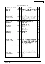
(1-2)The first line is black display in LCD
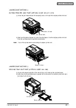
Connecting the low voltage
power unit with a PU board
(PRN PCB)
Cord Assembly connecting
the low voltage power unit
with a PU board (PRN PCB)
Connecting a PU board
(PRN PCB) with an operation
panel board (PRP PCB)
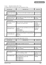
FFC connecting a PU board
(PRN PCB) with an Operation
panel board (PRP PCB)
Operation Panel Board
(PRP PCB)
3.3V power is offered to a PU
board (PRN PCB)
3.3V power which is offered to
PU board (PRN PCB)
I/F signal to the operation
panel board (PRP PCB) from
PU board (PRN PCB)
I/F signal to PU board
(PRN PCB) from the
operation panel board
(PRP PCB)
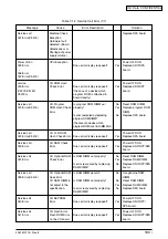
Confirmation Items
(1-2-1)Confirm connection systems
(1-2-2)Confirm the power systems
(1-2-3)3.3V power short
(1-2-4)Confirm the LSI operation
Confirmation Tasks
Confirm that a cord is correctly connected to POWER connector
of the PU board (PRN PCB) from low voltage power.
Check half connection or incomplete plug-in.
Check if it is disconnected.
Confirm that the cover is not removed.
Confirm cord assembly defects such as a lack of line materials.
Confirm that a line material supports the connection1pin-1pin.
Confirm that 9-pole FFC is correctly connected to OPE
connector of PU board (PRN PCB).
Confirm that 9-pole FFC is correctly connected to CN connector
of PU board (PRN PCB).
Check half connection or incomplete plug-in.
Check a disconnection with a tester. Confirm that the cover is
not removed by eyes.
Confirm whether to use a board of C5300/5100 (RSP PCB) for
the operation panel board.
Check 3.3V power with POWER connector 10,11,12pin of the
PU board (PRN PCB).
Confirm a short with POWER connector of the PU board.
10,11,12pin:3.3V
13,14,15,16,17pin:0VL
Perform a short check by plugging off LED head I/F cord from
CU board.
Perform a short check by separating CU board from PU board.
Confirm that a signal is outputted to OPE connector of PU board
(PRN PCB).
3pin:CLK
6pin: Sending data (Sending of PU board)
8pin:CLR
The signal is outputted all the time in a normal situation.
Confirm that a signal is outputted to OPE connector of PU board
(PRN PCB).
5pin:Receive data (Reception of PU board)
The signal is outputted all the time in a normal situation.
Action at NG
Plug in the cord
correctly.
Change it to a correct
cord.
Plug the cord correctly.
Exchange to a normal
FFC.
Exchange to
C5400/5200 board.
Exchange the low
voltage power.
Exchange the LED
head, CU board or PU
board.
Exchange the PU
board (PRN PCB).
Exchange the
operation panel board
(PRP PCB).
Summary of Contents for C3200n
Page 1: ...Oki Data CONFIDENTIAL C3200n C5150n C5200n C5400n C5510MFP Service Manual 060125A...
Page 2: ...42615101TH Rev 8 2 Oki Data CONFIDENTIAL...
Page 11: ...42615101TH Rev 8 11 Oki Data CONFIDENTIAL...
Page 13: ...42615101TH Rev 8 13 Oki Data CONFIDENTIAL...
Page 43: ...42615101TH Rev 8 43 Oki Data CONFIDENTIAL C5510 Handle Holes each on side or on end...
Page 65: ...42615101TH Rev 8 65 Oki Data CONFIDENTIAL Sample In case of C5200 C5150 C3200n...
Page 80: ...42615101TH Rev 8 80 Oki Data CONFIDENTIAL 1 2 3 4 5...
Page 84: ...42615101TH Rev 8 84 Oki Data CONFIDENTIAL 1 2 3 4 5 6 7 8 9 0 A B C...
Page 255: ...Oki Data CONFIDENTIAL 42615101TH Rev 8 255...


