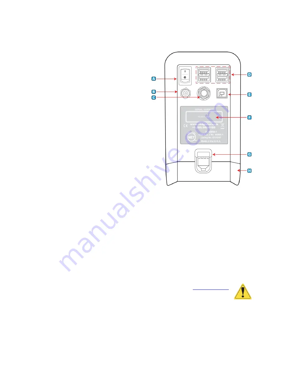
Instrument Setup
7
Instrument Rear Connections
A.
On-Off Switch
- The On-Off Switch functions like a
standard power switch. Toggle up ( | ) and the
power is turned on. Toggle the switch down (o) and
the power is turned off.
B.
12 VDC, 3A (max) Power Connection
- The power
connection is to supply power to the unit, and the
universal power supply shipped with the QuantiFit2
must be used.
C.
Trigger Button Connection
–
If the optional Trigger
Button is used to initiate test steps, it must be
inserted into this port.
D.
USB Devices (4
) - The four standard USB ports may
be used to connect a Keyboard, printer, USB
memory stick, or other useful devices.
E.
USB PC Port
- The USB PC Port is used to connect
the QuantiFit2 to a personal computer. The
QuantiFit2 is shipped with a supplied cable for this
purpose. The USB symbol on the cable must face up
to properly insert this cable. This
cable allows for the QuantiFit2 to be operated from the supplied software.
F.
Serial Number
–
Located in the center, the serial number is important should you require
service or support. All records are kept according to the serial number.
G.
Battery Latch
–
Push down on this latch to release the battery pack and pull outward to remove
it.
H.
Battery Pack
(optional) or
Cover
–
When using an optional battery pack to operate the
QuantiFit2, it will be inserted here. When no battery pack is purchased, this cavity will be filled
with a blank cover.
I.
Bluetooth Module
(internal, not shown) - When purchased with the Bluetooth function, the
QuantiFit2 can wirelessly connect to a computer with Bluetooth capability.
CAUTION: It is vital to open Logic software to pair the device. See
section.
OHD Logic software allows users to run multiple machines simultaneously, with flexibility on the
start time for any test. Standard Bluetooth allows testing to happen from across the room.
Summary of Contents for QuantiFit 2
Page 53: ...Appendix D CNP Diagram 52...
Page 108: ...Appendix D CNP Diagram 52...


