83
Position Control by Data Table
Overview
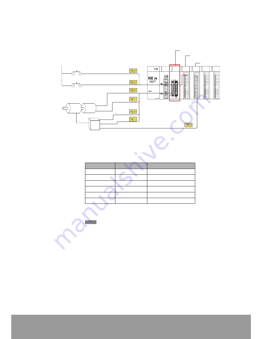
In the example, position is controlled as absolute values according to
the set values in data table.
Speed decreases 300 pulses before the stop point. Data table is
organized as follows, and deceleration point value (relative pulse
value) is also registered.
Also, pulse output is not used, and inverter start/stop is controlled by
CMP0 signal, and high/low speed is controlled by CMP1 signal.
Install Pulse I/O unit in slot No.0
Start input
(CH0 IN-A)
Count phase signals
from encoder.
(CH0 IN-B)
16 points output unit
0 V(24V DC)
(CMP1)
Occupied I/O area
R0
R1
R2
R3
R4
R5
Start/Stop
(CMP0)
Emergency stop
High/Low
Speed
Reverse instruction
Motor
Encoder
Inverte
16 points input unit
Address
Set value
Event
DT10, DT11
K 300
Speed turning point
DT12, DT13
K 2000
Target value 1
DT14, DT15
K -1500
Target value 2
DT16, DT17
K -2000
Target value 3
DT18, DT19
K 3000
Target value 4
DT20, DT21
K 0
Target value 5
For more precise measurements, pulse output function can be used and the
inverter can be replaced with a servo drive.
NOTE


