175
Pompa di calore ad inverter per piscine
IT
12
WARNING: Installation must be carried out by a qualified engineer.
This section is provided for information purposes only and must be checked and adapted if
necessary according to the actual installation conditions.
3.6 Hydraulic connection
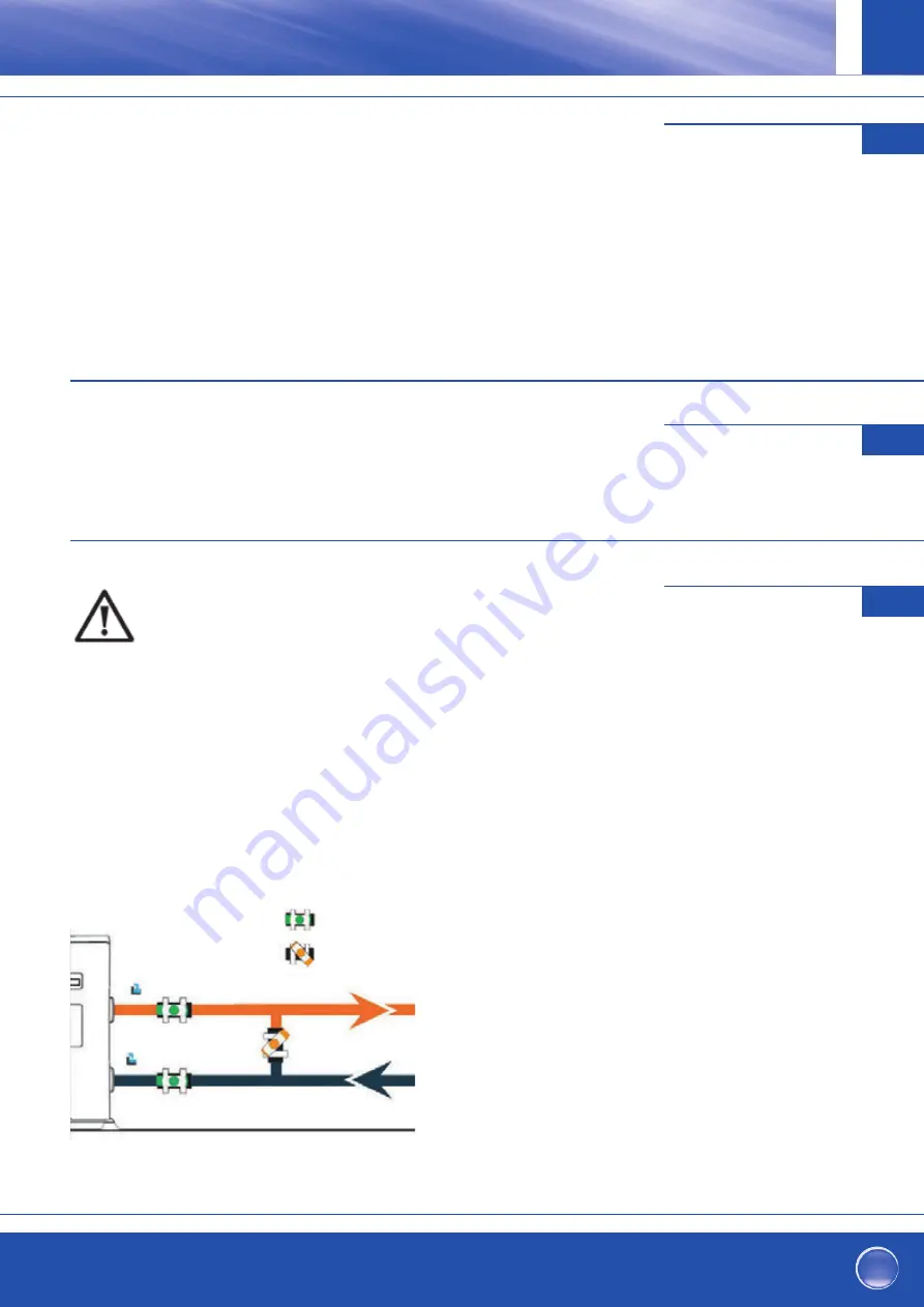
By-Pass assembly
The heat pump must be connected to the pool by means of a
By-Pass assembly.
A By-Pass is an assembly consisting of 3 valves that
regulate the flow circulating in the heat pump.
During maintenance operations, the By-Pass permits the heat
pump to be isolated from the system without interrupting your
installation.
Making a hydraulic connection with the By-Pass kit
WARNING: Do not run water through the hydraulic circuit for 2 hours after applying the adhesive.
Step 1: Take the necessary steps to cut your pipes.
Step 2: Make a straight perpendicular cut through the PVC pipes with a saw.
Step 3: Assemble your hydraulic circuit without connecting it in order to check that it perfectly fits your
installation, then dismantle the pipes to be connected. Step 4: Chamfer the ends of the cut pipes with sandpaper.
Step 5: Apply stripper to the ends of the pipes to be connected. Step 6: Apply the adhesive in the same place.
Step 7: Assemble the pipes.
Step 7: Clean off any adhesive remaining on the PVC.
Step 8: Leave to dry for at least 2 hours before putting the hydraulic circuit into water.
VERSO la piscina
DALLA piscina
Uscita
Ingresso
11
3.3 Installation layout
3.4 Connecting the condensation draining kit
While operating, the heat pump is subject to condensation. This will result in a more or less large run-off of
water, depending on the degree of humidity. To channel this flow, we recommend that you install the
condensation drainage kit.
How do you install the condensation drainage kit|?
Install the heat pump, raising it at least 10 cm with solid water-resistant pads, then connect the drainage pipe to
the opening located under the pump.
3.5 Installing the unit on noise-damping supports
In order to minimize the noise pollution associated with heat pump vibrations, it can be positioned on vibration
absorbing pads.
To do this, you simply have to position a pad between each of the unit’s feet and its support, and then fix
the heat pump to the support with suitable screws.
Valvola semichiusa
Valvola completamente
aperta
11
3.3 Installation layout
3.4 Connecting the condensation draining kit
While operating, the heat pump is subject to condensation. This will result in a more or less large run-off of
water, depending on the degree of humidity. To channel this flow, we recommend that you install the
condensation drainage kit.
How do you install the condensation drainage kit|?
Install the heat pump, raising it at least 10 cm with solid water-resistant pads, then connect the drainage pipe to
the opening located under the pump.
3.5 Installing the unit on noise-damping supports
In order to minimize the noise pollution associated with heat pump vibrations, it can be positioned on vibration
absorbing pads.
To do this, you simply have to position a pad between each of the unit’s feet and its support, and then fix
the heat pump to the support with suitable screws.
Durante il funzionamento della pompa di calore essa è soggetta alla formazione di con-
densa. Ciò provoca un defl usso d’acqua più o meno copioso a seconda dell'umidità dell'a-
ria. Per scaricare l'acqua di condensa, consigliamo di installare un kit di scarico condensa.
Come si installa il kit di scarico condensa?
Installare la pompa di calore sollevandola di almeno 10 cm con l'ausilio dei piedini (solidi,
resistenti all’umidità), quindi collegare il tubo di scarico e la boccola a corredo della pom-
pa di calore all’apertura tonda situata sotto/al fondo (vaschetta raccogli condensa) della
pompa.
Cfr. anche pagina 164, sezione 3.3 Posizione scarico condensa
Per ridurre al minimo il rumore provocato dalle vibrazioni della pompa di calore,
si consiglia appoggiarla su elementi elastici (ammortizzatori).
A questo scopo, porre un ammortizzatore tra ognuno dei piedini dell’apparecchio e la
fondazione, quindi fi ssare la pompa di calore sulla fondazione con delle apposite viti.
Collegamento del kit di
scarico di condensa
3.4
Installazione su ammortiz-
zatori di vibrazioni
3.5
Collegamento idraulico
3.6
AVVERTENZA IMPORTANTE:
L’installazione deve essere eff ettuata da un professionista.
Le informazioni fornite in questa sezione sono solo a titolo indicativo.
Perciò occorre verifi care le condizioni di installazione specifi che al luogo
di montaggio e, se necessario, adattarsi a queste.
Kit di by-pass
La pompa di calore deve essere collegata alla piscina via kit di by-pass.
Il kit by-pass è un modulo costituito da 3 valvole che consentono la regolazione della
circolazione dell’acqua all'interno della pompa di calore.
Durante interventi di manutenzione, le valvole di derivazione del modulo by-pass
consentono di isolare la pompa di calore dal sistema restante senza dover fermarlo.


