background image

Chapter 7: Maintenance 


AP-75036 - Revision 1.3 – 20/03/06 

153 

User’s Guide CS9000 series 


7.2.2 Weekly Maintenance 

 
At the end of the week, ink has to be removed from some parts, so it cannot harden.  Otherwise, some parts 
will break down or result in bad print quality. After performing a weekly maintenance, do not forget to perform 
the daily maintenance afterwards. 
 

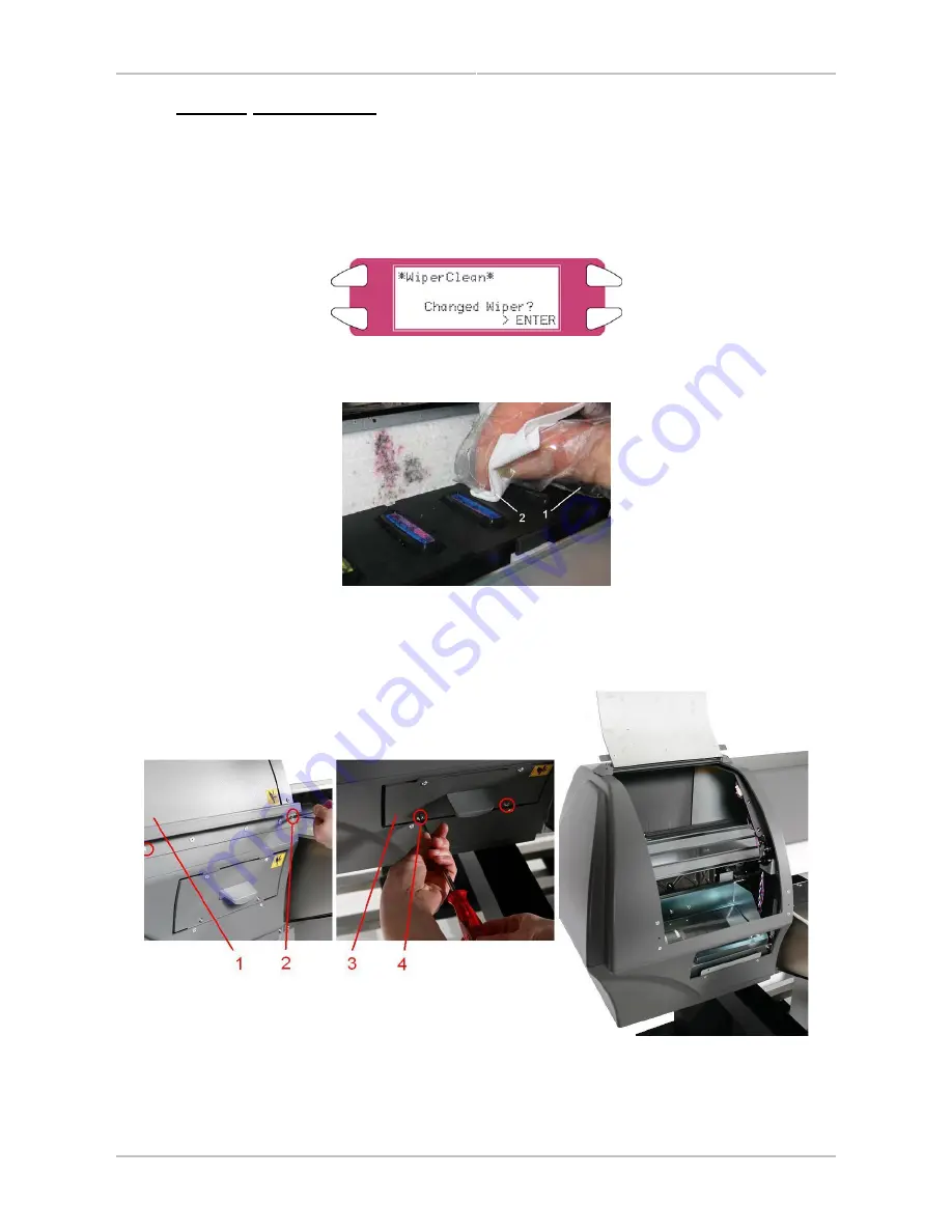
Step 1 : 

Power ON the printer and go to the “WiperClean-Menu”.  This will cause the unlocking of the 
carriage. 


Step 2 : 

Clean the area around the caps with a polyknit wiper.  If you see ink, dust or some thing else, 
clean it immediately so it can not influence the print quality. 


Gloves 

2 Polyknit 

wiper 


Step 3 : 

Open the left maintenance covers by loosening the four screws. 


Left Maintenance Cover 1 

Screws fixing left maintenance cover 1 

Left Maintenance Cover 2 

Screws fixing left maintenance cover 2 

Summary of Contents for CS9090

Page 1: ...Oc CS9065 Oc CS9090 User s Guide Low Solvent PRELIMINARY...

Page 2: ......

Page 3: ...rty to whom it is given assumes its custody and control and agrees to the following The information herein contained is given in confidence and any part thereof shall not be copied or reproduced witho...

Page 4: ......

Page 5: ...Ink for the first time 47 4 6 Media handling 52 4 7 Testprinting 59 4 8 Connecting the printer to your PC 65 4 9 Working with Oc s smartchip management system 68 5 Handling the printer 75 5 1 Introdu...

Page 6: ......

Page 7: ...duction 8 1 2 Warnings Cautions and Notes 8 1 3 Important safety instructions 8 1 4 Warning labels 11 1 4 1 Handling the warning labels 11 1 4 2 Locations and types of warning labels 11 1 4 2 1 Locati...

Page 8: ...y result in the printer tipping or falling over and causing injury Unstable surfaces Sloping floors Areas subject to vibration by other equipment Do not stand on or place heavy objects on your printer...

Page 9: ...Otherwise your eyes may become congested or inflamed slightly If you feel discomfort consult a doctor immediately Do not disassemble ink cassettes Otherwise ink may get in your eyes or on your skin Oc...

Page 10: ...r Lifting the printer with the vinyl cover on may cause your hands to slip and drop or damage the printer Have two or more people transport the printer Ensure that the plug has been disconnected from...

Page 11: ...sure to note the following when handling the labels Notes Make sure that all labels can be recognized If text or illustrations cannot be seen clearly either clean or replace the label When cleaning la...

Page 12: ...Chapter 1 Safety Instructions AP 75036 Revision 1 3 20 03 06 12 User s Guide CS9000 series No Type 1 2 3 4 7 5 6...

Page 13: ...er s Guide CS9000 series 8 9 10 1 4 2 2 Location and types of warning labels on back part No Type 3 CAUTION THIS UNIT HAS TWO POWER SUPPLY CORDS WHEN WiNDING UNIT IS PROVIDED TO REDUCE THE RISK OF ELE...

Page 14: ...Chapter 1 Safety Instructions AP 75036 Revision 1 3 20 03 06 14 User s Guide CS9000 series 1 5 LABELS IN FUNCTION OF TRANSPORTATION Nr Description 1 BEFORE powering on printer REMOVE dummy cartridges...

Page 15: ...2 3 3 Position and function of the heating elements 19 2 3 4 Operation panel 20 2 3 4 1 Operation keys 20 2 3 4 2 LCD monitor and light indicators 21 2 4 Printer status 22 2 4 1 Normal 22 2 4 2 Settin...

Page 16: ...ide variety of compatible media Adjustable head height can be adapted to various media thickness from 0 08 up to 1 1 mm 3 Vibrant Colour Reproduction To reproduce sharp and vivid colour 4 ink colours...

Page 17: ...hile it is operating Only open and or close the cover to perform following operations Media setting and replacement Cutter blade replacement Cleaning the cleaning wiper 3 Carriage Drives and holds the...

Page 18: ...r s Guide CS9000 series 2 3 2 Connections on the back No Connection 1 Ethernet connector 2 Card reader slot 3 Smartchip label 4 HardDisk bracket cover 5 Centronics connector 6 Foot switch connector 7...

Page 19: ...to make the prints touch dry Dryer Heater D 20 50 C The dryer completes the drying for compatibility with the take up in combination with higher output speeds Stickiness of printed banner materials i...

Page 20: ...ction assigned to F2 4 F3 key Executes the function assigned to F3 Executes the function assigned to F3 5 F4 key Executes the function assigned to F4 Executes the function assigned to F4 6 MENU key Ch...

Page 21: ...DATA lamp Orange OFF The printer is waiting to receive print data ON The pressure roller is in the release position Media has not been loaded 14 MEDIA SET lamp Orange OFF The pressure roller is in the...

Page 22: ...F4 key 6 Left of 4th line Displays the currently set media type 7 Right of 4th line Displays the approximate amount of remaining media that is currently set Units m However the amount is displayed onl...

Page 23: ...panel changes to the Setting menu display Notes Refer to Setup menu for details of the setting menu 2 4 3 2 Changing the status from the setting menu display to normal Take one of the following action...

Page 24: ......

Page 25: ...nder winder 100 29 3 2 4 Accessories box 29 3 2 5 Machine Starters Kit 30 3 2 6 User Maintenance kit for 6 months autonomy 31 3 3 Assembly 32 3 3 1 Assembling the stand 32 3 3 2 Installing the stand 3...

Page 26: ...uct Holding the unit over the vinyl plastic wrapping can result in slippage and dropping the unit resulting in damage The unpacking of the unwinder 100 system is described in its stand alone manual wh...

Page 27: ...he waste fluid tank 1 Outer board 2 Accessory box 3 Packaging box of the waste fluid tank 3 1 2 Unpacking stand packaging box Unpack the package of the stand according to the following procedure Step...

Page 28: ...e packages may be different depending on the market where they are used Contact your local Oc representative for details If any part is missing or broken contact either of the following The shop where...

Page 29: ...acket 1 7 Front tensioning bar 1 4 Right bracket 1 8 Rear tensioning bar 1 3 2 4 Accessories box No Description Quantity No Description Quantity 1 Power cable 1 2 Plain washers M6 16 6 Hexagon socket...

Page 30: ...Machine Starters Kit No Description Quantity 1 User Guide 1 2 Cd with manuals 1 3 Keyboard label 1 4 Heater label 1 5 Maintenance label set 6 languages 1 6 Harmful label 1 7 Low Solvent Setup Cleaning...

Page 31: ...omy Order number 29801288 Kit content No Description Quantity 1 Sponge plate 6 2 Wipers 24 3 Spitting box sponge 12 4 Cleaning Liquid 250 ml 3 5 Instruction sheet 1 6 Good shape kit 29801287 1 Good sh...

Page 32: ...to the following procedure Step 1 Place the stand upside down as shown in the figure Step 2 Install the foot to the stay according to the following procedure I Attach two feet on the bottom of the sta...

Page 33: ...nd with its feet on the floor Step 2 Lift up the main unit with at least four persons by holding it by the handles Step 3 Place the main unit on the stand 1 Stand 2 Main unit 3 Handle Step 4 Attach th...

Page 34: ...enclosed three types of spacers 5 pieces 0 3 mm spacer 5 pieces 0 5 mm spacer 5 pieces 1 0 mm spacer Procedure Step 1 Decide if the stand spacers are necessary using the table below IF THEN there is a...

Page 35: ...the product Step 2 Remove the two anti rubbing materials on the top of the main unit 1 Anti rubbing material Step 3 Remove the head unit fixture material from inside the front cover according to the f...

Page 36: ...75036 Revision 1 3 20 03 06 36 User s Guide CS9000 series IV Close the front cover 1 Front Cover 3 3 5 Installing the Unwinder Winder 100 Refer to the User s Guide in the box of the winding system to...

Page 37: ...4 1 1 Installation environment Requirements Choose a place for printer installation following the requirements in the table below 65 model 12 7m 144ft or larger Frontage of 4 7m 15 7ft or greater Area...

Page 38: ...though the condition is within the range written above Places where direct sunlight or excessive lighting are expected Places where air conditioners blow directly Oc recommends that the printer should...

Page 39: ...3 4 2 Installing the printer To install the product follow the steps below Step 1 Move the product to where it will be installed Step 2 Rotate the four adjusters in the direction shown in the figure t...

Page 40: ......

Page 41: ...tainers 58 4 7 Testprinting 59 4 7 1 Setup List 60 4 7 2 NozzleCheck 61 4 7 3 Alignment 62 4 7 4 Colour palette 63 4 7 5 Maintenance record 64 4 8 Connecting the printer to your PC 65 4 8 1 System req...

Page 42: ...ire The disconnect device is the plug on the power supply cord Caution Be careful of the following when handling the power cable o Do not make any modifications to the power cable o Do not place anyth...

Page 43: ...ire or an explosion o Earth terminals for telephone lines or lightening rods Doing so may cause a large flow of voltage if lightening occurs o Water pipes or faucets If there is a plastic part in the...

Page 44: ...place anything heavy on the foot switch o Do not bend the cable of the foot switch with force and do not pull o Do not place the foot switch near thermal devices Install the foot switch according to f...

Page 45: ...wing procedure Step 1 Press the POWER key of the operation panel to turn the unit ON The POWER lamp of the operation panel will light green Step 2 The unit will start initial start up operations Step...

Page 46: ...isplayed for 3 seconds on the operation panel Notes If pressing the POWER key on the operation panel by mistake press the POWER key again while the following message is displayed Step 4 The product wi...

Page 47: ...IJC910 Low Solvent ink and appropriate Low Solvent Cleaning Liquid Caution Before powering ON the unit make sure to Remove the dummy cassettes Remove the waste tube clamps Remove the bag enclosing the...

Page 48: ...on the display The CS9000 will start pumping air for about 15 seconds Step 4 The following message will be displayed Step 5 The head will be unlocked Moisten the caps with Low Solvent Cleaning Liquid...

Page 49: ...n the display below Step 8 Remove all Low Solvent Setup Cleaning cassettes when the message below appears Step 9 Install the 8 NEW Low Solvent Cleaning Liquid cassettes 2 as requested on the display S...

Page 50: ...appears Step 12 Insert the correct configuration of Oc IJC910 Low Solvent Ink cassettes as requested on the display The ink cassette must be put in a specific slot according to the type and colour use...

Page 51: ...e if the display mentions 0 minutes Step 14 Empty the Waste bottle when the display requests it Notes During ink installation note the following Do not power off the printer Do not unplug the power ca...

Page 52: ...ed to the printer wind the media up and then load the sheet media Step 1 Turn the printer on Step 2 The printer starts the initialize operation The following message is displayed on the operation pane...

Page 53: ...ith the media setting position Notes The media set position is a guideline for setting up the media If the right edge of the sheet media is 5 mm or more from the media setting position a media set err...

Page 54: ...de printing and lay down the media roll as shown in the images below Step 2 Position the media roll in the middle of the printing space Use the numbers indicated on the roll unit bar to position the m...

Page 55: ...2 Loading the media into the printer PART 1 INSTALLING AN EMPTY CORE AND LOADING THE MEDIA THROUGH THE REAR TENSIONING SYSTEM Step 1 Make sure the printer and UW W 100 are ON Step 2 Press the F4 key...

Page 56: ...r tensioning system will go to its initial position Step 5 Close the front cover Step 6 Start printing until the media reaches the front core of the winder OR feed the media without printing Step 7 Us...

Page 57: ...en loading sheet media Lever up Lever Down Up F3 Lever down Switches between up and down motion of the pressurizing lever Use this when starting over from the media setup User 1 User 2 User 3 User 4 U...

Page 58: ...e front cover Step 4 Install the media retainer left right to both sides of the roll media First attach the rear side of the media retainer to the rear of the print platform Step 5 Push the front side...

Page 59: ...pPrint is displayed on the LCD Step 5 Select an item and press the appropriate key Setup items Key name Parameters Descriptions F1 Setup Perform Setup List Refer to Setup List F2 Nozzle Check Perform...

Page 60: ...Chapter 4 Preparing for a job AP 75036 Revision 1 3 20 03 06 60 User s Guide CS9000 series 4 7 1 Setup List Use this function to check the current status of the printer...

Page 61: ...heck if there is any clogging of nozzles missing dots or faint printing Notes If printing quality declines or if missing dots are evident after the NozzleCheck the print heads need to be cleaned Refer...

Page 62: ...ON and set the media Step 2 Perform an accuracy adjustment printing for alignment according to TestPrinting When performing uni directional printing Alignment for the uni direction printing When perf...

Page 63: ...ser s Guide CS9000 series 4 7 4 Colour palette Use this function to compare the colour settings of the computer print colour of the printer This palette is printed in the mode you are currently workin...

Page 64: ...3 20 03 06 64 User s Guide CS9000 series 4 7 5 Maintenance record Use this function to check the life cycles of the printer parts Notes A part s life cycle is shown by the amount of the mark When a p...

Page 65: ...se a hard disk memory RAM as large as possible Please also refer to the recommendation made by the manufacturer of the RIP software you have selected 4 8 2 Selecting cables This printer is compatible...

Page 66: ...ter follow the steps below Step 1 Turn off the printer and your computer Step 2 Plug the cable connector of the interface cable into the interface connector at the back of the printer Squeeze the wire...

Page 67: ...rface cable Otherwise electrical shock or fire may occur o Do not touch the connector o Do not connect the network cable connector to the interface board having different specifications Step 1 Turn of...

Page 68: ...p cards of the cassettes will be transferred to the smartchip management system when using the printer mode 4 9 2 Explaining the smartchip management system Firmware incorporating the smartchip manage...

Page 69: ...ting the print data This ink volume transfer is AUTOMATICALY performed during printing Stage 1 Ink volume transfer BEFORE printing Stage 2 Ink volume transfer WHILE printing More info about Stage 2 In...

Page 70: ...cations are possible depending on the printer 1 On top of the printer Insert the smartchip card 1 in the printer s card reader slot 2 as shown on the image below 1 Smartchip card 2 Card reader slot 3...

Page 71: ...his case the user should manually set the colour mode that matches the ink set up See 4 9 5 Setting the colour mode on next page for more details 4 9 5 Setting the colour mode Step 1 Go to InkManager...

Page 72: ...is detected see display below remove the smartchip card and press ENTER no valid card is found see display below remove the smartchip card and press ENTER to scan the cassette slots in the printer Se...

Page 73: ...tion is performed when there is no valid ink card in the ink manager system s reader Notes In case there are 8 valid NOT empty smartchips installed on the printer this procedure should be repeated 8 t...

Page 74: ...Near end level 100ml o As the near end level has been reached for each job the operator manually needs to confirm that printing should be started ML consumption o Only when printing o 1 cumulative ml...

Page 75: ...11 Thickness menu 90 5 4 1 12 Heater menu 90 5 4 1 13 Fixer menu 91 5 4 1 14 Post Fixer menu 91 5 4 1 15 Drier menu 91 5 4 1 16 HStatus menu 92 5 4 1 17 Distance adjustment menu 92 5 4 1 18 Change men...

Page 76: ...5 4 4 5 Media width menu 111 5 4 4 6 Print and wipe menu 111 5 4 4 7 Smart Top Menu 111 5 4 4 8 Auto Cleaning Menu 112 5 4 4 9 Cap Cycle Menu 112 5 4 4 10 File management setup menu 112 5 4 4 11 Write...

Page 77: ...operation panel 129 5 5 1 Feeding media 129 5 5 2 Cleaning the heads 130 5 5 3 Controlling the heater elements 130 5 5 3 1 Change the heater temperature 131 5 5 3 2 Change the fixer temperature 131 5...

Page 78: ...se a software application 2 Power on the printer and load media into the printer Refer to Media handling Refer to Using Media 3 Select the preferred settings for printing with the printer Refer to Men...

Page 79: ...Notes Use recommended media in an appropriate environment Following are the appropriate temperature and humidity ranges for printing Temperature Humidity Recommended working environment 23 C 40 to 70...

Page 80: ...ing Notes Do not store media in high temperature high humidity or direct sunlight Store sheet media in the original bag after unpacking Unused roll media must be removed from the scroller rewound tigh...

Page 81: ...menu on the operation panel by following Menu setup on the operation panel I The following messages are displayed on the operation panel Step 2 Select an item from the list below and press the F1 or F...

Page 82: ...he operation panel Step 6 Press the F2 or F4 key on the operation panel to set the distance adjustment value based on the printing result in Step 3 Step 7 Press the ENTER key on the operation panel to...

Page 83: ...anel and setup items Follow the steps below to set the Menu settings Step 1 Make sure that the operation panel is normal Step 2 Press the MENU or MENU key I The screen shows following Menu Notes The N...

Page 84: ...work setting Makes the settings for the network interface Utility setting Makes various advanced function settings File management setting Makes various settings for the processing method of the print...

Page 85: ...e slots 1 3 Line 3 ink cassette slots 4 6 Line 4 ink cassette slots 7 8 Symbols Ink Colour K Black C Cyan M Magenta Y Yellow c Light Cyan m Light Magenta W Cleaning Liquid Type of Ink S Oc IJC910 Low...

Page 86: ...head position and media feed amount by operating the following keys F1 key Feeds media forward F2 key Moves the print head to the left F3 key Feeds media backward F4 key Moves the print head to the r...

Page 87: ...tems Parameters Description Type Sets the media type used for test printing Cut size To set the method for detecting the size of the media when sheet media has been loaded Top feed Sets the amount of...

Page 88: ...ems Parameters Description Thin Out Sets the amount of ink discharged while printing according to the media type InkDryTime In order to let the ink for the printing dry the time between the end of the...

Page 89: ...by operating the following keys F2 key to increase the setup value F4 key to decrease the setup value ENTER key to confirm the setup value CANCEL key to cancel the setup value 5 4 1 9 Head Height menu...

Page 90: ...eys F2 key to increase the setup value F4 key to decrease the setup value ENTER key to confirm the setup value CANCEL key to cancel the setup value Notes Bidirectional quality can only be obtained whe...

Page 91: ...50 C Change post fixer temperature by operating the following keys F2 key to increase the setup value F4 key to decrease the setup value ENTER key to confirm the setup value CANCEL key to cancel the...

Page 92: ...f 0 20 in steps of 0 10 is printed around the center of the correction value currently set Change Changes the media feed compensation value The menu changes to the Change Media Feed Correction Value m...

Page 93: ...sheet media is automatically detected Length When placing normal size sheet media vertically on the tray Width When placing normal size sheet media horizontally on the tray Cut Size After setting shif...

Page 94: ...cutting When Auto is selected proceed to the Shortest Cut Length menu If Manual or Off has been selected the screen changes to the menu of the previous hierarchy Notes For the situations shown below...

Page 95: ...e set Print mode setup CANCEL key to shift to the previous hierarchy menu 5 4 2 2 Print mode setup menu Perform various settings for Print mode For each setup value of Print mode four settings of Prin...

Page 96: ...pi 1440 2880dpi Condition 4 4 Diagonal 2880dpi The display changes to interlace setup items after the print quality items settings have been finished Condition 1 4 4 4 CANCEL key To shift to the previ...

Page 97: ...up items Parameters Description Times To set the number of repeats per line of printing Interval To set interval time for the repeat print Repeat CANCEL key To shift to the previous hierarchy menu 5 4...

Page 98: ...for the conditions of printer commands sent from the computer to the product Step To set the units for amount of movement for printing Position To set the initial writing position for printing Command...

Page 99: ...ers Description 0 010mm To set the printing units to 0 010mm 0 025mm To set the printing units to 0 025mm Print step To shift to the previous hierarchy menu Notes Please note that some software packag...

Page 100: ...tems Parameters Description 360dpi 600dpi 720dpi Image resolution 1 2 1080dpi 1200dpi 1440dpi 2160dpi Image resolution 2 2 2880dpi Makes settings for image resolution while printing with image data Im...

Page 101: ...rapid screening Quality High quality screening is performed according to the method of minimal average error Thin When printing data created for a competitor s printer make this setting if the Speed...

Page 102: ...imum and minimum values of the actual data and the data is located so that the center of the region is the same as the center of the media Layout method To shift to the previous hierarchy menu 5 4 2 2...

Page 103: ...CMY K menu Replace CMY values with K black Setup items Parameters Description No If MH GL GL2 are set on the Command Settings menu be sure to use CMY mixed colours ink If RTL PASS is set use both CMY...

Page 104: ...104 User s Guide CS9000 series 5 4 2 26 Mirror menu Set this to print reversed printing data Setup items Parameters Description Off No reversal of printing data Y axis ON For printing when data is rev...

Page 105: ...t to the previous hierarchy menu 5 4 3 2 Roll media length menu Set media roll length Setup items Parameters Description Roll media 1 4 1 m to 30 m to 99 m To change roll media length by operating the...

Page 106: ...1 2 DHCP To make the settings for the DHCP function of the network server MAC address The MAC address of the network interface board can be checked Network 2 2 Version The following software versions...

Page 107: ...menu of the previous hierarchy Refer to Network setting menu 5 4 3 7 Gateway menu The product sets the IP address of the connected gateway Setup items Parameters Description Gateway 000 000 000 000 2...

Page 108: ...MAC address of the network interface board MAC address To shift to the previous hierarchy menu 5 4 3 10 Version menu The following software versions of the network interface board can be checked Main...

Page 109: ...med for initial media to set the width of the media in the tray Print and Wipe To wipe while printing to take care of possible condensation on the print head nozzle plate SmartTop The ideal temperatur...

Page 110: ...is Rollfeed as a result of the standard unwinder winder 100 with your unit When setting Take up Mechanism on the Media Detection menu the following limits are applied to the operation of the product o...

Page 111: ...keys F2 key to increase the setup value F4 key to decrease the setup value ENTER key to confirm the setup value CANCEL key to cancel the setup value 5 4 4 6 Print and wipe menu To take care of possib...

Page 112: ...tle normal powerful a cleaning before every job CANCEL key to shift to the previous hierarchy menu 5 4 4 9 Cap Cycle Menu Perform a tubingflush every 1 to 24 hours Notes A tubingflush is automatically...

Page 113: ...1 Write mode menu To set the writing and printing method of printing data to the hard disk Notes Write mode menu has been displayed if a hard disk has been installed on the product When writing printi...

Page 114: ...s F1 key to select file name with back feed way F3 key to select file name with forward feed way Number 0 to 99 To change printing media number by operating the following keys F2 key Increases the set...

Page 115: ...ta Setup items Parameters Description Characters you want to change To select characters you want to change by operating the following keys F1 key To select characters you want to change with back fee...

Page 116: ...eleted Setup items Parameters Description No Format is not performed CANCEL key Cancels setup value shifts to the previous hierarchy menu Format Yes To perform formatting Setup items Parameters Descri...

Page 117: ...eturns parameters in the roll media setup menu to the factory setting Initialize 2 3 Centro Interface Returns parameters in the Centronics setup menu to the factory setting Network Returns parameters...

Page 118: ...ters Description NO No initialization OK To perform initialization Printing mode initialize After setting to shift to the previous hierarchy menu 5 4 4 20 Command setup Initialize menu Setup values of...

Page 119: ...etup items Parameters Description NO No initialization OK To perform initialization Roll media setup Initialize After setting to shift to the previous hierarchy menu 5 4 4 24 Centronics Initialize men...

Page 120: ...7 File management Initialize menu Setup values of File management menu are set to the factory default settings Setup items Parameters Description NO No initialization OK To perform initialization File...

Page 121: ...All Data Dump CANCEL key To exit Dump Mode To shift to the previous hierarchy menu 5 4 5 2 Ink Manager Menu Setup items Parameters Description Head Wash To perform a head cleaning Ink Load To load ink...

Page 122: ...k Load to load ink The process consists of several cleaning loadings several air loadings and one ink loading On the display of the operation panel a time indication is mentioned on the fourth line Me...

Page 123: ...onsumption of ink and cleaning liquid it is recommended to change ink types by using the Ink Change cycle The process consists of several cleaning loadings several air loadings and one ink loading On...

Page 124: ...Ink Discharge 3 Please insert Cleaning cart 4 During washing wait for a while 5 Ink not filled ALL 6 Power OFF 29 29 Notes When a cleaning cassettes is empty during LongStore procedure remove the empt...

Page 125: ...shifts to the previous menu Refer to Ink Manager menu 5 4 5 8 ChipManager menu Setup items Parameters Description Cassette Sets the printer in the cassette mode Printer Sets the printer in the printe...

Page 126: ...5 4 6 2 Wiper clean menu Clean the wipers Notes Refer to Cleaning the cleaning wiper for details regarding the procedure for cleaning the cleaning wiper Setup items Parameters Description No Do not c...

Page 127: ...ids out of the head nor out of the ink supply tubes Please refer to the Periodical Services for the daily and weekly maintenance of the CS 9000 The tubing flush feature includes following sequence 1 T...

Page 128: ...on 1 3 20 03 06 128 User s Guide CS9000 series 5 4 7 Setup Menu 7 7 5 4 7 1 Version Check menu Check the installed firmware and heater system version Setup items Parameters Description Version Check C...

Page 129: ...orward or backward follow the steps below Step 1 Verify the following regarding the condition of the printer I It is not currently printing Step 2 Press the F1 key of the operation panel I To shift to...

Page 130: ...s Key name Parameters Description F1 ALL Head 1 Head 2 Clean ALL heads or head couple one or two Cut Feed F2 Little normal powerful Set the intensity of a cleaning Step 4 Press the ENTER key to start...

Page 131: ...Press the ENTER key to confirm the requested temperature change Press the CANCEL key to leave the menu without changing the heater settings 5 5 3 3 Change the post fixer temperature To change the temp...

Page 132: ...the F4 key on the operation panel I The printer works as follows Status of the printer Operation after the F4 key has been pressed The pressure rollers have been lowered The MEDIA SET lamp turns off T...

Page 133: ...e displayed 5 6 2 When heaters are ready When heaters are ready the printer will start printing While printing some actions can be taken 1 1 1 3 1 On the fly step adjustments In case of overlapped pri...

Page 134: ...ep 2 Press the F1 key or the F2 key on the operation panel I The product will perform following operations Setup items Key name Parameters Description F1 ALL Head 1 Head 2 Clean ALL heads or head coup...

Page 135: ...OFF is set on the cut media menu If Take Up Roll has been set in the media detection setup menu When sheet media has been set Follow the steps below to cut the media Step 1 Make sure that the MEDIA S...

Page 136: ...dia is automatically transferred to the media cutting position Step 2 Press the F3 key on the operation panel I Shift to the cut and feed menu Step 3 Feed media to the desired position according to th...

Page 137: ...Error messages 144 6 3 1 Status messages 144 6 3 2 Message type error display and solutions 145 6 3 3 Data error display and solutions 146 6 3 4 Command error display and solutions 146 6 3 5 Error req...

Page 138: ...did not plug the power cable in Plug in the power cable Refer to Connecting the power cable 2 The AC power does not match the specified voltage Use the printer at the specified voltage Refer to Conne...

Page 139: ...Refer to Connecting the printer to your PC 5 Printouts are partially blurred or missing Notes You may not obtain reasonable quality with media other than recommended media No Possible cause Solutions...

Page 140: ...of the cutting blade is not sharp Replace the cutting blade Refer to Replacing the cutting blade 2 The roll media has static electricity Remove the static electricity on the roll media 3 Media is too...

Page 141: ...ing or liftoff Use the recommended media When using media other than recommended media set the following items in the media setting menu Media HeadHeight Stiff Refer to Media type Refer to Menu setup...

Page 142: ...t Refer to Product Specifications 5 You reused printed media Use new not printed media Refer to Media type 15 Media is crooked while printing No Possible cause Solutions References 1 You did not use r...

Page 143: ...lack lines on printouts No Possible cause Solutions References 1 You did not use recommended media Use recommended media Refer to Media type 19 Lines are missing No Possible cause Solutions References...

Page 144: ...ing data 5 Printing The printer is printing 6 Warning Waste Ink Tank Replace the waste liquid tank Refer to Replacing the waste liquid tank 7 Warning Ink Tube Life Contact the Oc s technical support c...

Page 145: ...n angle into the printer The printer stops Reload the media Refer to Loading media 3 End Of Roll Roll media runs out The printer stops Load new roll media Refer to Replacing media 4 Cover Open The fro...

Page 146: ...ing ink cassettes All All ink cassettes 6 3 3 Data error display and solutions Following are data errors and possible solutions during printer operations Data errors are displayed when a communication...

Page 147: ...rints and then stops see below 1 Power relating to the driving system is shut off automatically 2 All indicator lights on the operation panel are turned on and beeps sound continuously 3 An error mess...

Page 148: ...d on the operation panel Notes For raising or lowering the pressure rollers you can use the foot switch instead of the operation panel If a piece of media or media dust is stocked in the printer open...

Page 149: ...of the capping station 156 7 2 3 3 Replacing the sponge in the spitting box 157 7 3 Service done by authorised Oc technician 158 7 4 Replacing consumables 159 7 4 1 Replacing ink cassettes 159 7 4 2 R...

Page 150: ...rvice parts may be checked cleaned or replaced Perform periodical inspections according to the table below N Action Frequency 1 Clean wipers 2 Flush caps in maintenance station 3 Clean the edges of th...

Page 151: ...t harden Otherwise some parts will break down or result in bad print quality Notes In the box you will find a Good Shape Kit to perform the daily maintenance Normally this is enough for 6 months In ca...

Page 152: ...Liquid Step 6 Flush the caps until the colour of the mousse in the cap does not change anymore 1 Pipette 2 Caps Step 7 To stop the tubing flush cycle press enter I Check if ink is spoiled on the edge...

Page 153: ...daily maintenance afterwards Step 1 Power ON the printer and go to the WiperClean Menu This will cause the unlocking of the carriage Step 2 Clean the area around the caps with a polyknit wiper If you...

Page 154: ...ep 5 Clean the edges of the heads with a cleaning swab wetted by Low Solvent Cleaning Liquid Make sure you do not touch clean the nozzle plate this would lead to poorer print quality 1 Cleaning Swabs...

Page 155: ...ow Solvent Cleaning Liquid Step 5 Insert the moistened wiper with a pair of tweezers Be sure to insert the wiper correctly as shown below When standing in front of the machine Be sure that the wiper c...

Page 156: ...capping station Step 1 Power ON the printer and go to the WiperClean Menu This will cause the unlocking of the carriage Step 2 Remove the two screws fixing the sponge 1 Screws to remove the capping s...

Page 157: ...ob is done press the ENTER key and the head will lock again Step 2 The carriage moves to the waiting position for replacing the flushing sponge Step 3 Remove the old absorbents with tweezers 1 Sponge...

Page 158: ...L connection 14 1 Change capping station 15 1 Change cap assy maintenance station 16 as required Apply grease on head up down cams when needed 17 as required Apply grease on Y motor belt when needed...

Page 159: ...ed o Prepare new ink cassettes before they are totally empty b The ink cassette becomes empty o The following message is displayed on the operation panel o Printing operation stops o Replace with a ne...

Page 160: ...ow Solvent Ink and appropriate cleaning liquid Notes Do not disassemble ink cassettes Disassembled ink cassettes cannot be used Step 1 If the printer is turned on make sure of the following I Printing...

Page 161: ...not be able to print correctly Use up ink cassettes within two years from the date printed on the cassette packages Replace ink cassettes if after six months since installation Step 5 Install the ink...

Page 162: ...erations are not performed II Make sure that the display on the operation panel shows the normal status III The MEDIA SET light on the operation panel goes off Step 2 Follow Menu setup on the operatio...

Page 163: ...he cutting blade holder tab strongly or release it suddenly Doing so may cause the spring incorporated in the cutting blade holder to fly off Do not push in the cutting blade holder Doing so may cause...

Page 164: ...to fly off Do not push in the cutting blade holder Doing so may cause the cutting blade to damage the inside of the printer Attach the cutting blade holder lever correctly referring to the diagram bel...

Page 165: ...eps below to replace the waste liquid tank Step 1 Check the following if the power of the printer is ON I Printer is not printing II Operation panel is in normal status III Media setting light on the...

Page 166: ...pen the cap of a new waste liquid tank and put the tank to the printer Step 6 Press the ENTER key on the operation panel I The printer returns to menu 6 7 II The printer returns to the normal status b...

Page 167: ...r the printer OFF as soon as possible unplug the power cord and then contact your local Oc representative Caution Be sure to power OFF the printer and unplug the power cable from the outlet before cle...

Page 168: ...the inside of the printer Follow the steps below Step 1 Open the front cover 1 Front Cover Step 2 Use a soft brush to carefully clean away any dust or dirt on the pressure rollers Notes Do not blow o...

Page 169: ...rming head cleaning If you perform head cleaning with media installed the head may contact the media Step 1 Make sure that the state of the product is normal Caution Be sure not to pinch your fingers...

Page 170: ...When the head cleaning has been completed the printer returns to the normal status Notes We advise to let the printer rest for 5 10 minutes after a head cleaning procedure During that time the Low Sol...

Page 171: ...side the printer Also movement after transport is not covered by the warranty Have two or more people to transport the printer 1 Before the transfer If you are using the stand follow the steps below t...

Page 172: ...g the power cable Connecting the printer to your PC Step 3 Perform a nozzle check to check if the printer head has clogged Notes To perform the nozzle check refer to NozzleCheck Step 4 Perform a fine...

Page 173: ...r s Guide CS9000 series 8 APPENDIX 8 1 Introduction 174 8 2 Product Specifications 174 8 3 Interface Specifications 175 8 3 1 Centronics Bidirection Parallel Interface IEEE1284 Specifications 175 8 3...

Page 174: ...ng Print Modes Panel Control Options Uni Bi directional output Interweaving Mirror Output Multi Copy Ink Status Origin Control LCD Display Backlight LED 4 lines x 20 characters Take up System standard...

Page 175: ...STROBE To printer 19 SG 2 DATA1 To and from printer 20 SG 3 DATA2 To and from printer 21 SG 4 DATA3 To and from printer 22 SG 5 DATA4 To and from printer 23 SG 6 DATA5 To and from printer 24 SG 7 DATA...

Page 176: ...ifications Item Specifications Network Type Ethernet IEEE802 3 Network I F 10 Base T 100 Base TX automatic switching RJ 45 connector twisted pair cable y category 5 Protocol TCP IP Mode ftp lpr socket...

Page 177: ...AP 75036 Revision 1 3 20 03 06 177 User s Guide CS9000 series...

Reviews: