


OBO Bettermann
62 | EN
Mounting variants
6 4
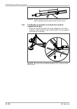
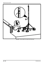
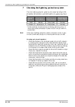
Lightning protection class I
The mounting example shows a better division of the lightning current
to two isCon
®
conductors through the use of an isFang air-termination
rod with two external cables
1
and
2
. The isCon
®
conductors are run
on two separated ring conductors
3
and
4
, which are run on opposite
sides of the building. Alternatively, the air-termination system can be
implemented with a single isCon
®
Premium cable in lightning protection
class 1.
The potential connection clip
5
(type 927 2 6-K) must be mounted, in
order to create an electrical connection between the jacket of the external
isCon
®
conductors and the air-termination rod. The potential is connected
here. Alternatively, the potential can be connected at the air-termination
rod stand
6
, providing that the potential connection clip
5
is mounted.
The distance x (= separation distance s multiplied by two) between the
potential connection terminals and the rear connection elements should
be noted.
Rd 8
Rd 8
1
4
5
6
3
2
x
x
Figure 67:
Current division to two isCon
®
conductors, e.g. for lightning protection
class I


