


OBO Bettermann
36 | EN
Installing the isCon® system
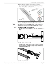
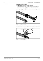
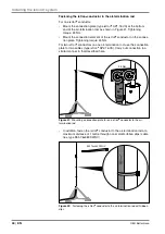
• Fix the connection element with a fork wrench (WAF 19 mm) and
screw the air-termination rod tight to the connection element.
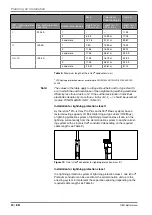
Figure 34:
Screwing the air-termination rod to the connection element
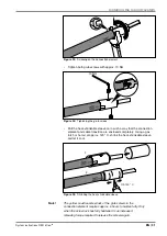
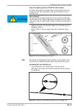
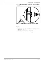
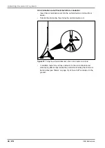
• Insert the bottom part of the air-termination rod into the air-termination
mast and fix with the side screw (20 Nm).
20 Nm
Figure 35:
Fixing the air-termination rod in the air-termination rod
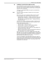
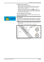
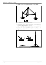
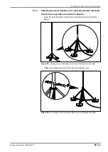
The internal potential connection element consists of two half shells.
These must be located in such a way that they surround the isCon
®
con-
ductor and one of the half shells is located centrally beneath the screw
holes, so that it can be pressed using the side screw (see Figure 38).
• Place the two half shells of the potential connection element on the
cable and push them into the retaining pipe.
Figure 36:
Attaching the internal potential connection element


