


OBO Bettermann
48 | EN
Installing the isCon® system
5 5
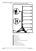
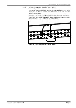
Routing the isCon
®
conductor
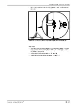
When routing the isCon
®
conductor to the forwarding conductor system,
observe the following information:
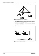
– The complete isCon
®
conductor must be located in the protection area
of the lightning protection system.
– The black cables may not be routed in the earth. They may not be
painted. Instead, use the grey isCon
®
ProPI 75 LGR cable.
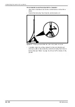
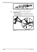
– Only use the accessories for fastening (see section 3.4.3 on page
18).
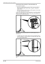
– The forwarding connection of the isCon
®
conductor may only be made
using the isCon
®
connect connection elements of the respective is-
Con
®
conductors.
– An isCon
®
conductor may not be extended.
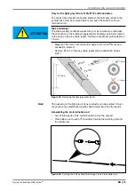
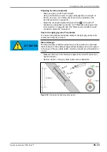
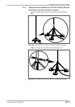
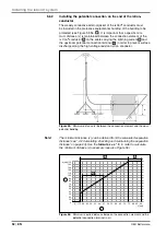
– When making route changes, maintain the minimum bend radius (see
Table 2 on page 10).
– Route the isCon
®
conductor in such a way that it cannot be damaged
by sharp-edged objects.
– If the isCon
®
conductor is damaged, the entire section must be re-
placed, as otherwise the correct function cannot be guaranteed. This
does not apply to the ProPlus 75 isCon
®
conductors. The ProPlus 75
variants may not have any damage or interruptions to the grey jacket
and/or rubber jacket. The exterior conductive layer may not be dam-
aged or interrupted.
– Ensure that the cable is connected to the equipotential bonding of the
structure as described in section 5.6. Create additional equipotential
bonding for metallic objects which cross or run in parallel (see section
5.6.4 on page 55).
– Special measures must be complied with for routing in potentially
explosive areas (see “„4.4 Installation in potentially explosive areas“ on
page 25).
– No point of the jacket of the isCon
®
conductor may come into contact
with parts carrying lightning current.
– Elements fastening the isCon
®
conductor may be spaced a maximum
of 1 metre apart.


