


OBO Bettermann
58 | EN
Mounting variants
6 Mounting variants
6 1
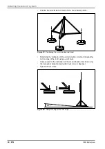
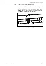
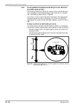
Separate lightning protection ring conductor
In the following example, the isCon
®
conductor
1
is to be connected to
a stand-off lightning protection ring conductor
2
. For this, we recom-
mend the air-termination rod stand with external isCon
®
conductor. This
is shortened to the right height using spacers
3
(type isCon
®
DH), run to
the ring conductor and connected, e.g. using Vario quick connectors.
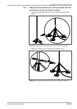
The potential is connected to the protective equipotential bonding on the
air-termination rod via the potential connection clip
4
(type 927 2 6-K).
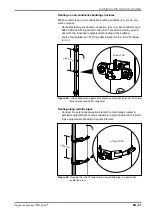
Alternatively, the potential can be connected at the air-termination rod
stand
5
, providing that the potential connection clip
4
is mounted,
creating the electrical connection between the outer jacket of the isCon
conductor and the air-termination rod.
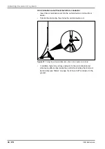
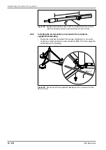
At the end of the isCon
®
conductor, the potential is connected with a
potential connection terminal
6
(type isCon
®
PAE) to the lightning protec-
tion ring conductor in front of the connection element
7
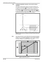
. The distance x
(= separation distance s multiplied by two) between the potential connec-
tion terminal
6
and the rear connection element
7
should be noted.
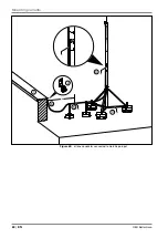
Note!
The isCon conductor, type BA 45 SW (Basic), can either be installed with
or without a potential connection. If the conductor is installed without a
potential connection, the distance x must be maintained between the con-
nection element and the last insulated spacer and from this last spacer
in the direction of the other end of the conductor. Within the calculated
separation distance s, there must be no electrically conductive parts.


