


OBO Bettermann
50 | EN
Installing the isCon® system
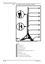
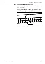
Internal isCon conductor
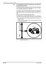
In the case of isFang air-termination rods with an internal isCon
®
conduct-
or, the potential connection must be connected via the potential connec-
tion element, which is located internally (see also Figure 36 and Figure
38). The potential connection must be brought into contact with the po-
tential connection element via the bottom screw and also with the weakly
conductive external jacket of the isCon
®
conductor.
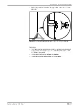
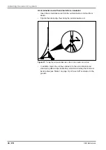
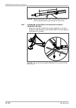
• Slacken the bottom screw as shown in Figure 53.
• Connect the protective equipotential bonding of the building to be pro-
tected with the internal potential connection element, e.g. with a cable
lug.
• Tighten the bottom screw again (20 Nm).
20 Nm
Figure 53:
Connecting the potential connection to the air-termination rod using a
cable lug


