


AN4536 Application Note Rev. 2.0 1/2014
2
Freescale Semiconductor
OTP Overview
2
OTP Overview
The regulators in the MMPF0100 have been designed with flexibility and configurability to allow them to be adapted
for a wide variety of applications. One-Time-Programmable (OTP) fuses in the MMPF0100 are used to exercise this
flexibility. Key startup parameters and regulator configuration information can be programmed into the MMPF0100
to enable it to power the system. These parameters are:
•
General
: I
2
C slave address, PWRON pin configuration, regulator start-up sequence and timing,
RESETBMCU configuration
•
Buck regulators
: Output voltage, dual/single phase or independent mode configuration, switching
frequency, and soft start ramp rate
•
Boost regulator and LDOs
: Output voltage
MMPF0100 starts up based on the contents of the TBBOTP registers. The TBBOTP registers can be loaded from
different sources as shown in
Table 1
. The default setting is hard-coded in the MMPF0100 and is available in all
non-programmed and programmed MMPF0100 devices. Once OTP programming is complete, TBBOTP can be
either loaded from the default values or from the OTP fuses.
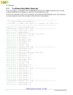
The OTP block in the MMPF0100 also features a ‘Try-Before-Buy’ (TBB) mode which allows experimentation with
different voltages and sequences of the regulators. In the TBB mode, TBBOTP registers are directly written to and
used for startup of the MMPF0100. Contents of the TBBOTP registers can be maintained in the absence of the main
input supply, VIN, by using a coin cell at the LICELL pin.
2.1
Power-up Configuration
The PF0100 powers up based on the contents of the TBBOTP registers. Depending on certain pin and bit settings,
the TBBOTP registers are loaded from different sources as shown in
Table 1
.
The TBBOTP registers serve as temporary storage for any of the following:
1.
The values to be written to the fuses, or
2.
The values read from the fuses, or
3.
The values to start from during TBB development, or
4.
The values read from the default configuration.
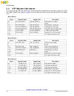
The TBBOTP registers are located within the Extended Page 1 of the MMPF0100 register map.
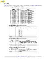
Table 1. Power-up Configuration Source and Conditions
Source
Condition
Power-Up Configuration
ROM
VDDOTP = VCOREDIG
(1)
MMPF0100 starts up using the factory default settings
TBBOTP Registers
VDDOTP = 0 V and TBB_POR = 1
MMPF0100 starts up from current values of TBBOTP
registers. This is referred to as the 'Try-Before-Buy'
mode
OTP Fuses
VDDOTP = 0 V and
TBB_POR = 0 and FUSE_POR_XOR = 1
(2)
The MMPF0100 starts up from the OTP fuse values
Notes:
1. Pull-up VDDOTP to VCOREDIG with a 100 k resistor.
2. In MMPF0100, FUSE_POR1, FUSE_POR2 and FUSE_POR3 are XOR’ed into the FUSE_POR_XOR bit. The FUSE_POR_XOR has to be
1 for fuses to be loaded. This can be achieved by setting any one or all of the FUSE_PORx bits. In MMPF0100A, the XOR function is
removed. It is required to set all of the FUSE_PORx bits to be able to load the fuses.