


AN4536 Application Note Rev. 2.0 1/2014
18
Freescale Semiconductor
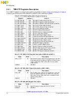
OTP Overview
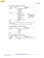
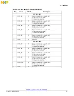
Table 24. OTP PU CONFIGx Bits Definition
Bit
Name
Description
1:0
SEQ_CLK_SPEEDx[1:0]
Sequence delay between steps, bits are XORed
00 = 500
μ
s
01 = 1000
μ
s
10 = 2000
μ
s
11 = 4000
μ
s
3: 2
SWDVS_CLKx[1:0]
Start-up slew rate, bits are XOR'd
00 = 25 mV/2
μ
s
01 = 25 mV/4
μ
s
10 = 25 mV/8
μ
s
11 = 25 mV/16
μ
s
4
PWRON_CFGx
Set the power on button initial configuration
0 = Power button is level sensitive
1 = Power button is edge sensitive and turn-off is based on time held low
7:5
RSVD
Reserved
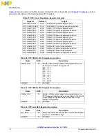
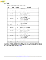
Table 25. OTP_PU_CONFIG XOR Bits Definition
Bit
Name
Description
1:0
SEQ_CLK_SPEED_XOR
Final result of the XOR function of the SEQ_CLK_SPEEDx[1:0] bits
3: 2
SWDVS_CLK_XOR
Final result of the XOR function of the SWDVS_CLKx[1:0] bits
4
PWRON_CFG_XOR
Final result of the XOR function of the SEQ_PWRON_CFGx bits
7:5
RSVD
Reserved
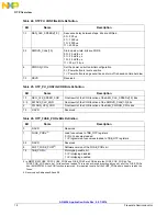
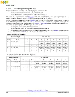
Table 26. OTP_FUSE_PORx Bits Definition
Bit
Name
Description
0
RSVD
Reserved
1
FUSE_PORx
(5)
Load fuse values to TBB_OTP registers
0 = No Fuse value loaded
1 = Programmed fuse values loaded to TBB_OTP registers
5:2
RSVD
Reserved
6
SOFT_FUSE_POR
(6)
Software version of the FUSE_PORx bit
7:5
TBB_POR
(6)
Prototyping enable bit
0 = Prototyping disabled
1 = Prototyping enabled
5. In MMPF0100 FUSE_POR1, FUSE_POR2 and FUSE_POR3 are XOR’ed into the FUSE_POR_XOR bit. The
FUSE_POR_XOR has to be 1 for fuses to be loaded. This can be achieved by setting any one or all of the FUSE_PORx
bits. In MMPF0100A, the XOR function is removed. It is required to set all of the FUSE_PORx bits to be able to load the
fuses.
6. Reserved on Addresses E5 and E6